
Page 24 - Handbook of Materials Failure Analysis
P. 24
16 CHAPTER 1 Progressive failures of components
Heat exchanger
Distillation column
Filter
grid
Filter of pump
discharge
Centrifugal pump
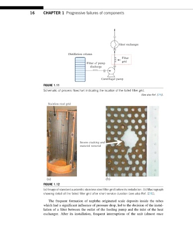
FIGURE 1.11
Schematic of process flowchart indicating the location of the failed filter grid.
(See also Ref. [24]).
Stainless steel grid
Severe cracking and
material removal
(a) (b)
FIGURE 1.12
(a) Image of standard austenitic stainless steel filter grid before its installation. (b) Macrograph
showing detail of the failed filter grid after short service duration (see also Ref. [24]).
The frequent formation of naphtha originated scale deposits inside the tubes
which had a significant influence of pressure drop, led to the decision of the instal-
lation of a filter between the outlet of the feeding pump and the inlet of the heat
exchanger. After its installation, frequent interruptions of the unit (almost once