
Page 19 - Handbook of Materials Failure Analysis
P. 19
3 Case Studies 11
(a) (b)
(c) (d)
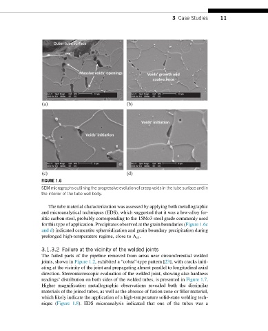
FIGURE 1.6
SEM micrographs outlining the progressive evolution of creep voids in the tube surface and in
the interior of the tube wall body.
The tube material characterization was assessed by applying both metallographic
and microanalytical techniques (EDS), which suggested that it was a low-alloy fer-
ritic carbon steel, probably corresponding to the 15Mo3 steel grade commonly used
for this type of application. Precipitates observed at the grain boundaries (Figure 1.6c
and d) indicated cementite spheroidization and grain boundary precipitation during
prolonged high-temperature regime, close to A c1 .
3.1.3.2 Failure at the vicinity of the welded joints
The failed parts of the pipeline removed from areas near circumferential welded
joints, shown in Figure 1.2, exhibited a “cobra”-type pattern [23], with cracks initi-
ating at the vicinity of the joint and propagating almost parallel to longitudinal axial
direction. Stereomicroscopic evaluation of the welded joint, showing also hardness
readings’ distribution on both sides of the welded tubes, is presented in Figure 1.7.
Higher magnification metallographic observations revealed both the dissimilar
materials of the joined tubes, as well as the absence of fusion zone or filler material,
which likely indicate the application of a high-temperature solid-state welding tech-
nique (Figure 1.8). EDS microanalysis indicated that one of the tubes was a