
Page 16 - Handbook of Materials Failure Analysis
P. 16
8 CHAPTER 1 Progressive failures of components
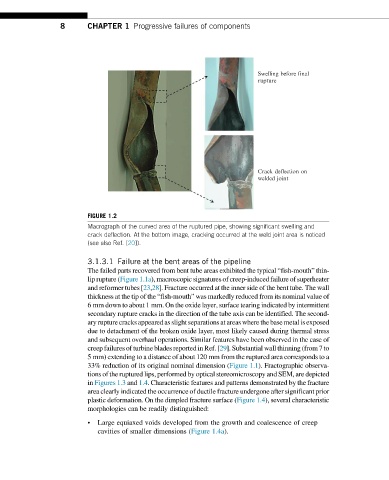
Swelling before final
rupture
Crack deflection on
welded joint
FIGURE 1.2
Macrograph of the curved area of the ruptured pipe, showing significant swelling and
crack deflection. At the bottom image, cracking occurred at the weld joint area is noticed
(see also Ref. [20]).
3.1.3.1 Failure at the bent areas of the pipeline
The failed parts recovered from bent tube areas exhibited the typical “fish-mouth” thin-
lip rupture (Figure 1.1a), macroscopic signatures of creep-induced failure of superheater
and reformer tubes [23,28]. Fracture occurred at the inner side of the bent tube. The wall
thickness at the tip of the “fish-mouth” was markedly reduced from its nominal value of
6 mm down to about 1 mm. On the oxide layer, surface tearing indicated by intermittent
secondary rupture cracks in the direction of the tube axis can be identified. The second-
aryrupture cracks appearedas slightseparations atareaswhere thebase metalis exposed
due to detachment of the broken oxide layer, most likely caused during thermal stress
and subsequent overhaul operations. Similar features have been observed in the case of
creep failures of turbineblades reportedin Ref. [29]. Substantial wall thinning (from7 to
5 mm) extending to a distance of about 120 mm from the ruptured area corresponds to a
33% reduction of its original nominal dimension (Figure 1.1). Fractographic observa-
tions of the ruptured lips, performed by optical stereomicroscopy and SEM, are depicted
in Figures 1.3 and 1.4. Characteristic features and patterns demonstrated by the fracture
area clearly indicated the occurrence of ductile fracture undergone after significant prior
plastic deformation. On the dimpled fracture surface (Figure 1.4), several characteristic
morphologies can be readily distinguished:
• Large equiaxed voids developed from the growth and coalescence of creep
cavities of smaller dimensions (Figure 1.4a).