
Page 18 - Handbook of Materials Failure Analysis
P. 18
10 CHAPTER 1 Progressive failures of components
• Elongated dimples corresponding to the initial grain alignment due to the
directionality of the manufacturing process (Figure 1.4b).
• Isolated areas of transgranular cleavage fracture and slip bands appeared in the
interior of the dimples (Figure 1.4c).
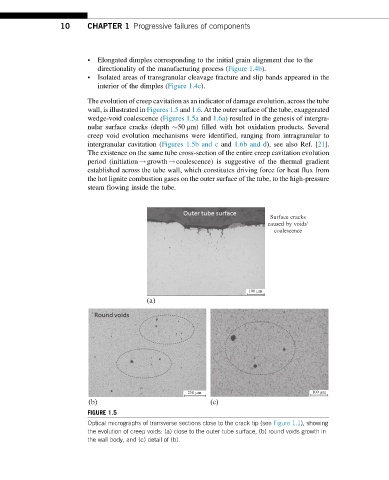
The evolution of creep cavitation as an indicator of damage evolution, across the tube
wall, is illustrated in Figures 1.5 and 1.6. At the outer surface of the tube, exaggerated
wedge-void coalescence (Figures 1.5a and 1.6a) resulted in the genesis of intergra-
nular surface cracks (depth 50 μm) filled with hot oxidation products. Several
creep void evolution mechanisms were identified, ranging from intragranular to
intergranular cavitation (Figures 1.5b and c and 1.6b and d), see also Ref. [21].
The existence on the same tube cross-section of the entire creep cavitation evolution
period (initiation!growth!coalescence) is suggestive of the thermal gradient
established across the tube wall, which constitutes driving force for heat flux from
the hot lignite combustion gases on the outer surface of the tube, to the high-pressure
steam flowing inside the tube.
Surface cracks
caused by voids’
coalescence
100 µm
(a)
250 µm 100 µm
(b) (c)
FIGURE 1.5
Optical micrographs of transverse sections close to the crack tip (see Figure 1.1), showing
the evolution of creep voids: (a) close to the outer tube surface, (b) round voids growth in
the wall body, and (c) detail of (b).