
Page 22 - Handbook of Materials Failure Analysis
P. 22
14 CHAPTER 1 Progressive failures of components
Round voids’ formation
Acc.V Spot Magn Det WD 500 µm Acc.V Spot Magn Det WD 100 µm
20.0 kV 3.0 71x SE 5.6 20.0 kV 3.0 250x SE 5.4
(a) (b)
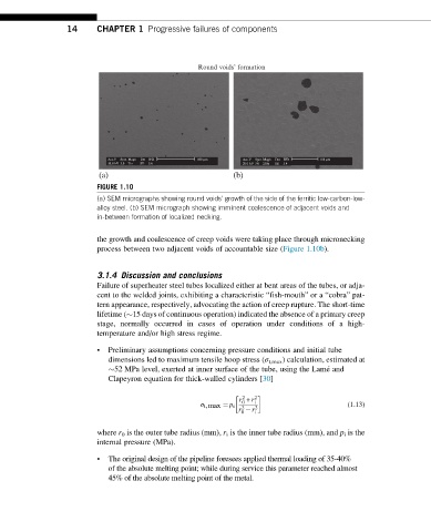
FIGURE 1.10
(a) SEM micrographs showing round voids’ growth of the side of the ferritic low-carbon-low-
alloy steel. (b) SEM micrograph showing imminent coalescence of adjacent voids and
in-between formation of localized necking.
the growth and coalescence of creep voids were taking place through micronecking
process between two adjacent voids of accountable size (Figure 1.10b).
3.1.4 Discussion and conclusions
Failure of superheater steel tubes localized either at bent areas of the tubes, or adja-
cent to the welded joints, exhibiting a characteristic “fish-mouth” or a “cobra” pat-
tern appearance, respectively, advocating the action of creep rupture. The short-time
lifetime ( 15 days of continuous operation) indicated the absence of a primary creep
stage, normally occurred in cases of operation under conditions of a high-
temperature and/or high stress regime.
• Preliminary assumptions concerning pressure conditions and initial tube
dimensions led to maximum tensile hoop stress (σ t,max ) calculation, estimated at
52 MPa level, exerted at inner surface of the tube, using the Lame ´ and
Clapeyron equation for thick-walled cylinders [30]
r + r i
2 2
0
σ t,max ¼ p i 2 2 (1.13)
r r i
0
where r 0 is the outer tube radius (mm), r i is the inner tube radius (mm), and p i is the
internal pressure (MPa).
• The original design of the pipeline foresees applied thermal loading of 35-40%
of the absolute melting point; while during service this parameter reached almost
45% of the absolute melting point of the metal.