
Page 361 - Handbook of Properties of Textile and Technical Fibres
P. 361
334 Handbook of Properties of Textile and Technical Fibres
HO
OH O OH
HO HO
O O O O
O HO OH O
HO
OH
Cellulose l
OH
OH O OH
HO HO
O O O O
HO
O OH O
OH OH
Cellulose Il
Figure 10.4 Patterns of intrachain hydrogen bonding in Cellulose I and II.
in native cellulosics, only the adjacent chains in sheets are linked (Northolt et al.,
2001). The crystalline structure in native cellulosics is labeled “Cellulose I,” whereas
that in regenerated cellulosics is labeled “Cellulose II.”
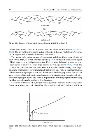
The tensile deformation curves of regenerated cellulosic fibers resemble that of
other textile fibers, as shown illustratively in Fig. 10.5. There is an initial linear region
of high slope up to a yield point at around 1% extension, followed by a second near-
linear region of relatively lower slope beyond the yield point (Northolt, 1985). The
deformation processes up to the yield point is believed to involve mainly the straight-
ening and orientation of polymer chains along the fiber axis without significant rupture
of intermolecular hydrogen bonds, and this deformation is largely elastic. Beyond the
yield point, a plastic deformation is observed, which is attributed to rupture of inter-
molecular hydrogen bonds and relative displacement between polymer chains along
the fiber axis, ultimately leading to fiber breakage.
Given the differences of hydrogen bonding patterns between the two crystalline
forms, their inherent moduli also differ. The tensile moduli of Cellulose I and II are
Stress
Yield point
Strain
Figure 10.5 Illustration of a typical tensile stressestrain measured on a regenerated cellulosic
fiber.