
Page 67 - Handbook of Properties of Textile and Technical Fibres
P. 67
48 Handbook of Properties of Textile and Technical Fibres
for Materials and Structures on the tensile properties of the concrete by diametrical
compression. Since this conference, such types of diametral compression tests are
often called “Brazilian” tests. Applied to fibers, this experiment is also known as
the single fiber transverse compression test (SFTCT) (Hadley et al., 1965; Phoenix
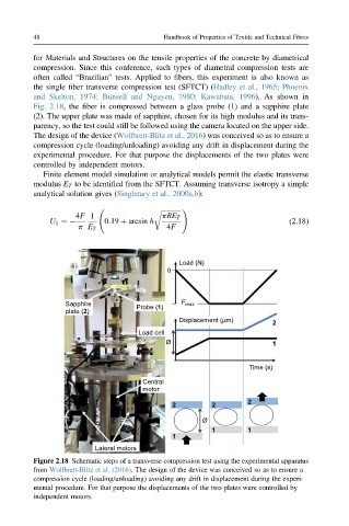
and Skelton, 1974; Bunsell and Nguyen, 1980; Kawabata, 1996). As shown in
Fig. 2.18, the fiber is compressed between a glass probe (1) and a sapphire plate
(2). The upper plate was made of sapphire, chosen for its high modulus and its trans-
parency, so the test could still be followed using the camera located on the upper side.
The design of the device (Wollbrett-Blitz et al., 2016) was conceived so as to ensure a
compression cycle (loading/unloading) avoiding any drift in displacement during the
experimental procedure. For that purpose the displacements of the two plates were
controlled by independent motors.
Finite element model simulation or analytical models permit the elastic transverse
modulus E T to be identified from the SFTCT. Assuming transverse isotropy a simple
analytical solution gives (Singletary et al., 2000a,b):
ffiffiffiffiffiffiffiffiffiffiffiffi !
r
4F 1 pRE T
U 1 ¼ 0:19 þ arcsin h (2.18)
p E T 4F
Load (N)
0
Sapphire Probe (1) F max
plate (2)
Displacement (μm) 2
Load cell
Ø 1
Time (s)
Central
motor
2 2 2
Ø
1 1
1
Lateral motors
Figure 2.18 Schematic steps of a transverse compression test using the experimental apparatus
from Wollbrett-Blitz et al. (2016). The design of the device was conceived so as to ensure a
compression cycle (loading/unloading) avoiding any drift in displacement during the experi-
mental procedure. For that purpose the displacements of the two plates were controlled by
independent motors.