
Page 241 - Handbook of Structural Steel Connection Design and Details
P. 241
Welded Joint Design and Production
226 Chapter Three
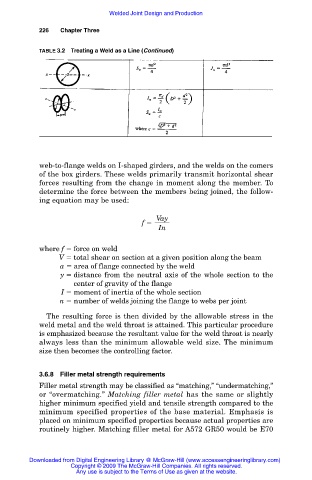
TABLE 3.2 Treating a Weld as a Line (Continued)
web-to-flange welds on I-shaped girders, and the welds on the comers
of the box girders. These welds primarily transmit horizontal shear
forces resulting from the change in moment along the member. To
determine the force between the members being joined, the follow-
ing equation may be used:
Vay
f
In
where f force on weld
V total shear on section at a given position along the beam
a area of flange connected by the weld
y distance from the neutral axis of the whole section to the
center of gravity of the flange
I moment of inertia of the whole section
n number of welds joining the flange to webs per joint
The resulting force is then divided by the allowable stress in the
weld metal and the weld throat is attained. This particular procedure
is emphasized because the resultant value for the weld throat is nearly
always less than the minimum allowable weld size. The minimum
size then becomes the controlling factor.
3.6.8 Filler metal strength requirements
Filler metal strength may be classified as “matching,” “undermatching,”
or “overmatching.” Matching filler metal has the same or slightly
higher minimum specified yield and tensile strength compared to the
minimum specified properties of the base material. Emphasis is
placed on minimum specified properties because actual properties are
routinely higher. Matching filler metal for A572 GR50 would be E70
Downloaded from Digital Engineering Library @ McGraw-Hill (www.accessengineeringlibrary.com)
Copyright © 2009 The McGraw-Hill Companies. All rights reserved.
Any use is subject to the Terms of Use as given at the website.