
Page 310 - Handbook of Structural Steel Connection Design and Details
P. 310
Partially Restrained Connections
Partially Restrained Connections 295
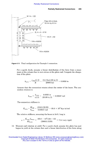
W 14 × 120
Plate 3/4-in thick,
16.5 in by 9.5 in
2L 4 × 4 × 5/16
W 21 × 62
7/8 in A325X
7/8 in A325X
Figure 4.10 Final configuration for Example 1 connection.
For a quick check, assume a linear distribution of the force from a maxi-
mum at the column face to zero stress at the plate end. Compute the elonga-
tion of the plate:
s slip sL>2d s14.3 ksids20 in>2d
conn 5 5 5 0.0050 in
E 29000 ksi
Assume that the connection rotates about the center of the beam. The con-
nection rotation is
conn 0.0050 in
conn 5 5 5 0.00047 rad
sd>2d s20.99 in>2d
The connection stiffness is
s2141ds20.99d
M slip 6
K conn 5 5 5 95.6 3 10 kip- in/rad
conn 0.00047 rad
The relative stiffness, assuming the beam is 24 ft. long is
6
s95.6 3 10 ds24 3 12d
K conn L beam
5 5 5 714 (very rigid)
EI beam s29000ds1330d
12. Moment and rotation at yield: For a quick check assume the plate has just
begun to yield at the column face and a linear distribution of the force along
Downloaded from Digital Engineering Library @ McGraw-Hill (www.accessengineeringlibrary.com)
Copyright © 2009 The McGraw-Hill Companies. All rights reserved.
Any use is subject to the Terms of Use as given at the website.