
Page 315 - Handbook of Structural Steel Connection Design and Details
P. 315
Partially Restrained Connections
300 Chapter Four
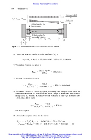
1.2w + 0.5W L
D
V gravity =
V = V gravity +V lateral 2L v
h
V lateral = 2M p,beam
Critical section for L v
beam design
V , M pb
h
Critical section for
connection design
L = L – d – 2S
S h v c h S h
d c
Figure 4.14 Increase in moment at connection critical section.
6. The actual moment at the face of the column (M ) is
f
M f 5 M pr 1 V h S h 5 17,585 1 s145.1ds25d 5 21,212 kip-in
7. The actual force on the plate is
21,212 kip-in
F plate 5 5 765.0 kips
27.7 in
8. Recheck the number of bolts
F plate 765.8
n $ 5 5 13.0, 14 bolts is ok
v sF v A b d s1.00ds0.785 3 75d
9. Determine the size of the flange plate, assuming that the plate width will be
somewhere between the widths of the beam flange (9.99 in) and the column
flange (16.2 in). Assume distance between bolts is 5 in and edge distances are
4.0 in. Try a 13-in plate:
F plate 765.8
t f 5 5 5 1.18 in
d F y b s1.0ds50ds13d
use 1.25-in plate
10. Check net and gross areas for the plate:
F gross area 5 R y F y A gross 5 s1.1ds50ds13 3 1.25d 5 894 kips
F net area 5 F y A net 5 s65ds13 2 2s1.125dd 3 1.25d 5 873 kips ok
Downloaded from Digital Engineering Library @ McGraw-Hill (www.accessengineeringlibrary.com)
Copyright © 2009 The McGraw-Hill Companies. All rights reserved.
Any use is subject to the Terms of Use as given at the website.