
Page 312 - Handbook of Structural Steel Connection Design and Details
P. 312
Partially Restrained Connections
Partially Restrained Connections 297
10000
9000
8000
7000
Moment (kip-in) 5000
6000
4000
3000
2000
1000
0
0 5 10 15 20
Rotation (mrad)
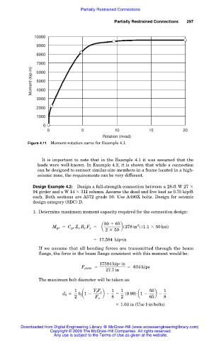
Figure 4.11 Moment-rotation curve for Example 4.1.
It is important to note that in the Example 4.1 it was assumed that the
loads were well-known. In Example 4.2, it is shown that while a connection
can be designed to connect similar-size members in a frame located in a high-
seismic zone, the requirements can be very different.
Design Example 4.2: Design a full-strength connection between a 28-ft W 27
94 girder and a W 14 311 column. Assume the dead and live load as 0.75 kip/ft
each. Both sections are A572 grade 50. Use A490X bolts. Design for seismic
design category (SDC) D.
1. Determine maximum moment capacity required for the connection design:
50 1 65
3
M pr 5 C pr Z x R y F y 5 a bs278 in d s1.1 3 50 ksid
2 3 50
5 17,584 kip-in
If we assume that all bending forces are transmitted through the beam
flange, the force in the beam flange consistent with this moment would be:
17584 kip- in
F plate 5 5 634 kips
27.7 in
The maximum bolt diameter will be taken as:
1 Y t F y 1 1 50 1
d b # b f a1 2 b 2 5 s9.99d a1 2 b 2
2 F u 8 2 65 8
5 1.03 in sUse 1- in boltsd
Downloaded from Digital Engineering Library @ McGraw-Hill (www.accessengineeringlibrary.com)
Copyright © 2009 The McGraw-Hill Companies. All rights reserved.
Any use is subject to the Terms of Use as given at the website.