
Page 318 - Handbook of Structural Steel Connection Design and Details
P. 318
Partially Restrained Connections
Partially Restrained Connections 303
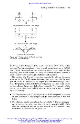
(a) Deformation on flexible T-stub flange
Q B B Q
a b
b' a'
(b) Forces on flexible T-stub flange
M p
M
(c) Hinges on T-stub flange
Figure 4.15 Prying action in T-stub, showing
the case of a flexible flange.
thickness of the flanges and the location and size of the bolts to the
column. The big advantage of this type of connection over a CW-BB
one is that these springs can provide a much larger deformation
capacity than a weld would. A T-stub connection can thus provide a
good balance between strength, stiffness, and ductility.
The design of a T-stub connection essentially follows the same
steps as for the CW-BB connections described previously (for the stem
portion of the connection) with important additional design provi-
sions for prying action, bolt tensile elongation capacity, local effects
on the column flange, and bolt shear strength. The strength of the
connection to the column, taking into account prying action, is limited
by the following:
The bending strength of the flanges of the T: This depends primarily
on the thickness of the flanges and the exact location of the bolt
holes.
The ultimate tensile strength of the stem of the T: The net area gen-
erally governs over the gross area criteria because the width of the
stem at the critical section for net area is not too different from
that of the critical section for gross area.
Downloaded from Digital Engineering Library @ McGraw-Hill (www.accessengineeringlibrary.com)
Copyright © 2009 The McGraw-Hill Companies. All rights reserved.
Any use is subject to the Terms of Use as given at the website.