
Page 321 - Handbook of Structural Steel Connection Design and Details
P. 321
Partially Restrained Connections
306 Chapter Four
Q
d
b a
2T
B = T + Q
b' a'
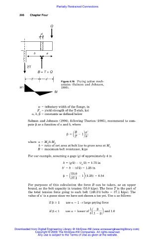
Figure 4.16 Prying action mech-
anisim (Salmon and Johnson,
M1 1995).
M
w tributary width of the flange, in
F yield strength of the T-stub, ksi
y
, , constants as defined below
Salmon and Johnson (1996), following Thorton (1985), recommend to com-
pute as a function of and , where
B a
5 a 2 1b
T b
where M / M
1 2
ratio of net area at bolt line to gross area at M
1
B maximum bolt resistance, kips
For our example, assuming a gage (g) of approximately 4 in
b (g/2) (t /2) 1.75 in
w
b b (d/2) 1.25 in
53.0
5 a 2 1bs1.25d 5 0.54
37.1
For purposes of this calculation the force B can be taken, as an upper
bound, as the bolt capacity in tension (53.0 kips). The force T is the part of
the total tension force going to each bolt (148.3/4 bolts 37.1 kips). The
value of a is a guess since we have not chosen a tee yet. Use as follows:
if 1 use 1 → large prying force
1
if < 1 use lesser of a b and 1.0
1 2
Downloaded from Digital Engineering Library @ McGraw-Hill (www.accessengineeringlibrary.com)
Copyright © 2009 The McGraw-Hill Companies. All rights reserved.
Any use is subject to the Terms of Use as given at the website.