
Page 325 - Handbook of Structural Steel Connection Design and Details
P. 325
Partially Restrained Connections
310 Chapter Four
L = x sp @ s vb L gh
vb
d vk
W T-stub g vb
t ft d th
g tb
t st
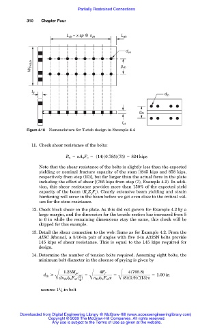
Figure 4.18 Nomenclature for T-stub design in Example 4.4
11. Check shear resistance of the bolts:
R n 5 nA b F v 5 s14ds0.785ds75d 5 824 kips
Note that the shear resistance of the bolts is slightly less than the expected
yielding or nominal fracture capacity of the stem [(845 kips and 858 kips,
respectively from step (10)], but far larger than the actual force in the plate
including the effect of shear [(765 kips from step (7), Example 4.2). In addi-
tion, this shear resistance provides more than 150% of the expected yield
capacity of the beam (R Z F ). Clearly extensive beam yielding and strain
y x y
hardening will occur in the beam before we get even close to the critical val-
ues for the stem resistance.
12. Check block shear on the plate. As this did not govern for Example 4.2 by a
large margin, and the dimension for the tensile section has increased from 5
to 6 in while the remaining dimensions stay the same, this check will be
skipped for this example.
13. Detail the shear connection to the web: Same as for Example 4.2. From the
AISC Manual, a 5/16-in pair of angles with five 1-in A325N bolts provide
145 kips of shear resistance. This is equal to the 145 kips required for
design.
14. Determine the number of tension bolts required. Assuming eight bolts, the
minimum bolt diameter in the absence of prying is given by
4s765.8d
4F f
1.25M pr
d tb $ 5 5 5 1.00 in
Bdn tb n F nt s d Bn tb n F nt Bs8ds0.9ds113d
4
1
assume 1 / 4 -in bolt
Downloaded from Digital Engineering Library @ McGraw-Hill (www.accessengineeringlibrary.com)
Copyright © 2009 The McGraw-Hill Companies. All rights reserved.
Any use is subject to the Terms of Use as given at the website.