
Page 324 - Handbook of Structural Steel Connection Design and Details
P. 324
Partially Restrained Connections
Partially Restrained Connections 309
16.00
5.00
1.73
3.00
8.16
3.00
25.00 3.00
3.00
3.00 27.75
3.00
6.00
2.00 12.00
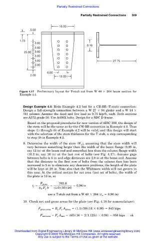
Figure 4.17 Preliminary layout for T-stub cut from W 40 264 beam section for
Example 4.4.
Design Example 4.4: Redo Example 4.2 but for a CB-BB (T-stub) connection:
Design a full-strength connection between a W 27 94 girder and a W 14
311 column. Assume the dead and live load as 0.75 kip/ft, each. Both sections
are A572 grade 50. Use A490X bolts. Design for a SDC D frame.
Based on the proposed procedures for new version of AISC 358, the design of
the stem will be the same as for the CW-BB connection in Example 4.2. Thus
steps (1) through (8) of Example 4.2 will be valid, and this design will start
with the selection of the stem thickness for the T stub, a step corresponding
to step (9) in Example 4.2.
9. Determine the width of the stem (W ), assuming that the stem width will
T
vary between something larger than the width of the beam flange (9.99 in,
say 12 in) at the beam end and somewhat less than the column flange width
(16.2 in, say 16 in) at the last row of bolts (see Fig. 4.17). Assume gage
between bolts is 6 in and edge distances are 2.0 in at the beam end. Assume
that the distance to the first row of bolts from the column face has been
increased to 5 in to eliminate any clearance problems; the length of the plate
will be kept at 28 in. Note also that the Whitmore width will not govern in
this case. At the critical section for net area (last set of bolts), the width of
the plate is 16 in, so
765.8
F plate
t f 5 5 5 0.96 in
d F y b s1.0ds50ds16d
use a T-stub cut from a W 40 3 264 st w 5 0.96 ind
10. Check net and gross areas for the plate (see Fig. 4.18 for nomenclature):
F gross area 5 R y F y A gross 5 s1.1ds50ds16 3 0.96d 5 845 kips
F net area 5 F y A net 5 s65ds16 2 2s1.125dd 3 0.96d 5 858 kips ok
Downloaded from Digital Engineering Library @ McGraw-Hill (www.accessengineeringlibrary.com)
Copyright © 2009 The McGraw-Hill Companies. All rights reserved.
Any use is subject to the Terms of Use as given at the website.