Page 327 - Handbook of Structural Steel Connection Design and Details
P. 327

Partially Restrained Connections

                    312   Chapter Four

                          b. For a mixed failure mode, with a plastic mechanism followed by fracture
                            of the bolts is

                                           d r nt a     d pF y t ft 2
                                    T 2 5      1          $ T reqd
                                        a  1 b   4sa  1 b d
                                        s1.00ds104.3ds2.50d  s1.00ds4.00ds50ds1.73d 2
                                          5             1
                                           s2.50 1 1.29d    s4ds2.50 1 1.29d
                                           5 68.8 1 39.5 5 108.3 kip/bolt

                          c. For the limit state of bolt fracture without yielding of the tension flange,
                            the design resistance per tension bolt is calculated as
                                   T 3 5   d r nt 5 s1.00ds104.3 kip/boltd 5 104.3  kip/bolt

                            Compute the net capacity of the tension flange is

                              R n 5 n tb  T 5 n tb  T 3 5 s8 boltsds104.3 kip/boltd 5 834.4 kips . F pr
                                 5 765.8 kips     ok
                      17. In addition to the checks above for the connection itself, the column must be
                         checked for following limit states: (1) panel zone shear, (2) need for continuity
                         plates, (3) local web yielding, (4) web crippling, (5) compression buckling of the
                         web, and (6) local flange bending.

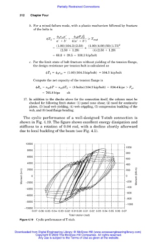
                      The cyclic performance of a well-designed T-stub connection is
                    shown in Fig. 4.19. The figure shows excellent energy dissipation and
                    stiffness to a rotation of 0.04 rad, with a decline shortly afterward
                    due to local buckling of the beam (see Fig. 4.1).


                        10000
                                                                               1000
                        8000
                                                                               800
                        6000
                                                                               600
                        4000
                                                                               400
                        2000
                                                                               200
                      Moment (k-in)  0                                         0 –200  Moment (kN-m)

                        –2000
                                                                               –400
                        –4000
                                                                               –600
                        –6000
                                                                               –800
                        –8000
                                                                               –1000
                       –10000
                          –0.07–0.06–0.05–0.04–0.03–0.02–0.010.00 0.01 0.02 0.03 0.04 0.05 0.06 0.07
                                               Total rotation (rad)
                    Figure 4.19 Cyclic performance of T stub.


                 Downloaded from Digital Engineering Library @ McGraw-Hill (www.accessengineeringlibrary.com)
                             Copyright © 2009 The McGraw-Hill Companies. All rights reserved.
                              Any use is subject to the Terms of Use as given at the website.
   322   323   324   325   326   327   328   329   330   331   332