
Page 61 - Handbook of Structural Steel Connection Design and Details
P. 61
Design of Connections for Axial, Moment, and Shear Forces
46 Chapter Two
R 0.75 [F A min {0.6 F A , 0.6 F A }]
bs u nt y gv u nv
0.75 [58 1.03 min {0.6 36 21.75,
0.6 58 15.66}] 4
1590 kips > 855 kips ok
This completes the design checks for the brace-to-gusset con-
nection. All elements of the load path, which consists of the
bolts, the brace web, the gusset, and the connection angles,
have been checked. The remaining connection interfaces require
a method to determine the forces on them. Research (Thornton
1991, 1995b) and practice (AISC, 2005) have shown that the best
method for doing this is the uniform force method (UFM). The
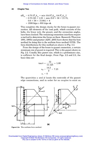
force distributions for this method are shown in Fig. 2.3.
From the design of the brace-to-gusset connection, a certain
minimum size of gusset is required. This is the gusset shown in
Fig. 2.2. Usually, this gusset size, which is a preliminary size,
is sufficient for the final design. From Figs. 2.2 and 2.3, the
basic data are
12
tan
5 5 1.08
11.125
14.3
e 5 5 7.15
B
2
e 5 0
c
The quantities and locate the centroids of the gusset
edge connections, and in order for no couples to exist on
Figure 2.3a The uniform force method.
Downloaded from Digital Engineering Library @ McGraw-Hill (www.accessengineeringlibrary.com)
Copyright © 2009 The McGraw-Hill Companies. All rights reserved.
Any use is subject to the Terms of Use as given at the website.