
Page 92 - Handbook of Structural Steel Connection Design and Details
P. 92
Design of Connections for Axial, Moment, and Shear Forces
Design of Connections for Axial, Moment, and Shear Forces 77
not included in bracing connection design, except implicitly as noted here
to justify replacing |H H | A with max (H , A).
C D C
2.2.1.6 Load paths have consquences. The UFM produces a load path
that is consistent with the gusset plate boundaries. For instance, if the
gusset-to-column connection is to a column web, no horizontal force is
directed perpendicular to the column web because unless it is stiffened,
the web will not be able to sustain this force. This is clearly shown in
the physical test results of Gross (1990) where it was reported that
bracing connections to column webs were unable to mobilize the column
weak axis stiffness because of web flexibility.
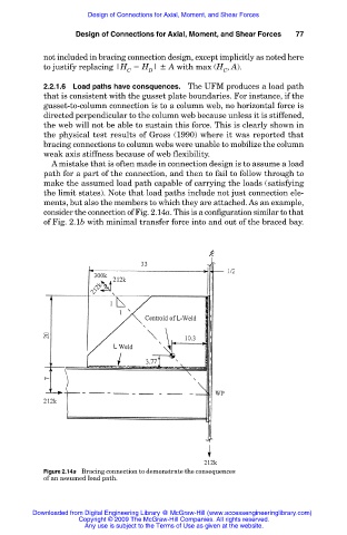
A mistake that is often made in connection design is to assume a load
path for a part of the connection, and then to fail to follow through to
make the assumed load path capable of carrying the loads (satisfying
the limit states). Note that load paths include not just connection ele-
ments, but also the members to which they are attached. As an example,
consider the connection of Fig. 2.14a. This is a configuration similar to that
of Fig. 2.1b with minimal transfer force into and out of the braced bay.
Figure 2.14a Bracing connection to demonstrate the consequences
of an assumed load path.
Downloaded from Digital Engineering Library @ McGraw-Hill (www.accessengineeringlibrary.com)
Copyright © 2009 The McGraw-Hill Companies. All rights reserved.
Any use is subject to the Terms of Use as given at the website.