
Page 93 - Handbook of Structural Steel Connection Design and Details
P. 93
Design of Connections for Axial, Moment, and Shear Forces
78 Chapter Two
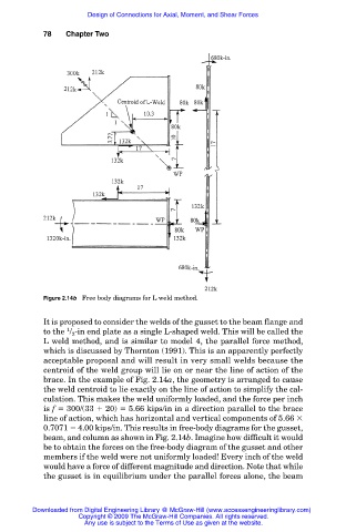
Figure 2.14b Free body diagrams for L weld method.
It is proposed to consider the welds of the gusset to the beam flange and
1
to the / -in end plate as a single L-shaped weld. This will be called the
2
L weld method, and is similar to model 4, the parallel force method,
which is discussed by Thornton (1991). This is an apparently perfectly
acceptable proposal and will result in very small welds because the
centroid of the weld group will lie on or near the line of action of the
brace. In the example of Fig. 2.14a, the geometry is arranged to cause
the weld centroid to lie exactly on the line of action to simplify the cal-
culation. This makes the weld uniformly loaded, and the force per inch
is f 300/(33 20) 5.66 kips/in in a direction parallel to the brace
line of action, which has horizontal and vertical components of 5.66
0.7071 4.00 kips/in. This results in free-body diagrams for the gusset,
beam, and column as shown in Fig. 2.14b. Imagine how difficult it would
be to obtain the forces on the free-body diagram of the gusset and other
members if the weld were not uniformly loaded! Every inch of the weld
would have a force of different magnitude and direction. Note that while
the gusset is in equilibrium under the parallel forces alone, the beam
Downloaded from Digital Engineering Library @ McGraw-Hill (www.accessengineeringlibrary.com)
Copyright © 2009 The McGraw-Hill Companies. All rights reserved.
Any use is subject to the Terms of Use as given at the website.