
Page 90 - Handbook of Structural Steel Connection Design and Details
P. 90
Design of Connections for Axial, Moment, and Shear Forces
Design of Connections for Axial, Moment, and Shear Forces 75
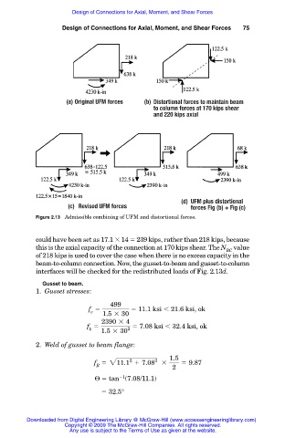
(a) Original UFM forces (b) Distortional forces to maintain beam
to column forces at 170 kips shear
and 220 kips axial
(d) UFM plus distortional
(c) Revised UFM forces forces Fig (b) + Fig (c)
Figure 2.13 Admissible combining of UFM and distortional forces.
could have been set as 17.1 14 239 kips, rather than 218 kips, because
this is the axial capacity of the connection at 170 kips shear. The N value
BC
of 218 kips is used to cover the case when there is no excess capacity in the
beam-to-column connection. Now, the gusset-to-beam and gusset-to-column
interfaces will be checked for the redistributed loads of Fig. 2.13d.
Gusset to beam.
1. Gusset stresses:
499
f 11.1 ksi 21.6 ksi, ok
v
1.5 3 30
2390 3 4
f 7.08 ksi 32.4 ksi, ok
b 2
1.5 3 30
2. Weld of gusset to beam flange:
1.5
2
2
f 211.1 1 7.08 3 5 9.87
R
2
1
Θ tan (7.08/11.1)
32.5°
Downloaded from Digital Engineering Library @ McGraw-Hill (www.accessengineeringlibrary.com)
Copyright © 2009 The McGraw-Hill Companies. All rights reserved.
Any use is subject to the Terms of Use as given at the website.