
Page 85 - Handbook of Structural Steel Connection Design and Details
P. 85
Design of Connections for Axial, Moment, and Shear Forces
70 Chapter Two
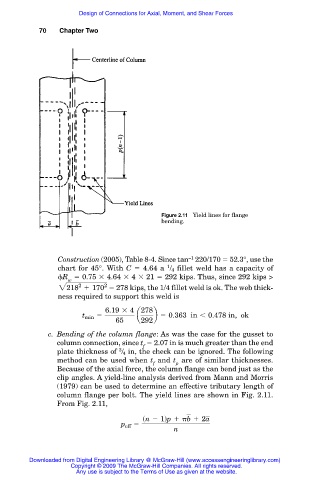
Figure 2.11 Yield lines for flange
bending.
Construction (2005), Table 8-4. Since tan 220/170 52.3°, use the
–1
chart for 45°. With C 4.64 a / 4 fillet weld has a capacity of
1
R 0.75 4.64 4 21 292 kips. Thus, since 292 kips >
w
2
2218 1 170 2 278 kips, the 1/4 fillet weld is ok. The web thick-
ness required to support this weld is
6.19 3 4 278
t min 5 a b 5 0.363 in , 0.478 in, ok
65 292
c. Bending of the column flange: As was the case for the gusset to
column connection, since t 2.07 in is much greater than the end
f
3
plate thickness of / 4 in, the check can be ignored. The following
method can be used when t and t are of similar thicknesses.
f p
Because of the axial force, the column flange can bend just as the
clip angles. A yield-line analysis derived from Mann and Morris
(1979) can be used to determine an effective tributary length of
column flange per bolt. The yield lines are shown in Fig. 2.11.
From Fig. 2.11,
sn 2 1dp 1 b 1 2a
p eff 5
n
Downloaded from Digital Engineering Library @ McGraw-Hill (www.accessengineeringlibrary.com)
Copyright © 2009 The McGraw-Hill Companies. All rights reserved.
Any use is subject to the Terms of Use as given at the website.