
Page 9 - Handbook of Surface Improvement and Modification
P. 9
4 Scratch and Mar Resistance
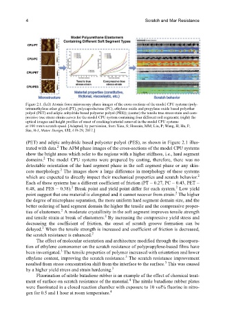
Figure 2.1. (left) Atomic force microscopy phase images of the cross-sections of the model CPU systems (poly-
tetramethylene ether glycol (PT), polycaprolactone (PC), ethylene oxide and propylene oxide based polyether
polyol (PET) and adipic anhydride based polyester polyol (PES)); (center) the tensile true stress-stain and com-
pressive true stress-strain curves for the model CPU system containing four different soft segments; (right) the
optical images and height profiles of onset of cracking/material removal in the model CPU systems
at 100 mm/s scratch speed. [Adapted, by permission, from Xiao, S; Hossain, MM; Liu, P; Wang, H; Hu, F;
Sue, H-J, Mater. Design, 132, 419-29, 2017.]
(PET) and adipic anhydride based polyester polyol (PES), as shown in Figure 2.1 illus-
2
trated with data. The AFM phase images of the cross-sections of the model CPU systems
show the bright areas which refer to the regions with a higher stiffness, i.e., hard segment
2
domains. The model CPU systems were prepared by casting, therefore, there was no
detectable orientation of the hard segment phase in the soft segment phase or any skin-
2
core morphology. The images show a large difference in morphology of these systems
which are expected to directly impact their mechanical properties and scratch behavior. 2
Each of these systems has a different coefficient of friction (PT − 0.27, PC − 0.43, PET −
2
2
0.48, and PES − 0.38). Break point and yield point differ for each system. Low yield
2
point suggest that one material is elongated and it cannot recover from strain. The higher
the degree of microphase separation, the more uniform hard segment domain size, and the
better ordering of hard segment domain the higher the tensile and the compressive proper-
2
ties of elastomers. A moderate crystallinity in the soft segment improves tensile strength
2
and tensile strain at break of elastomers. By increasing the compressive yield stress and
decreasing the coefficient of friction, the onset of scratch groove formation can be
2
delayed. When the tensile strength is increased and coefficient of friction is decreased,
2
the scratch resistance is enhanced.
The effect of molecular orientation and architecture modified through the incorpora-
tion of ethylene comonomer on the scratch resistance of polypropylene-based films have
3
been investigated. The tensile properties of polymer increased with orientation and lower
3
ethylene content, improving the scratch resistance. The scratch resistance improvement
3
resulted from stress concentration shift from the interface to the surface. This was caused
3
by a higher yield stress and strain hardening.
Fluorination of nitrile butadiene rubber is an example of the effect of chemical treat-
4
ment of surface on scratch resistance of the material. The nitrile butadiene rubber plates
were fluorinated in a closed reaction chamber with exposure to 10 vol% fluorine in nitro-
4
gen for 0.5 and 1 hour at room temperature.