
Page 11 - Handbook of Surface Improvement and Modification
P. 11
6 Scratch and Mar Resistance
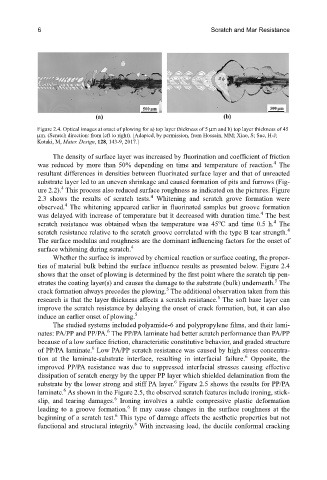
Figure 2.4. Optical images at onset of plowing for a) top layer thickness of 5 μm and b) top layer thickness of 45
μm. (Scratch direction: from left to right). [Adapted, by permission, from Hossain, MM; Xiao, S; Sue, H-J;
Kotaki, M, Mater. Design, 128, 143-9, 2017.]
The density of surface layer was increased by fluorination and coefficient of friction
4
was reduced by more than 50% depending on time and temperature of reaction. The
resultant differences in densities between fluorinated surface layer and that of unreacted
substrate layer led to an uneven shrinkage and caused formation of pits and furrows (Fig-
4
ure 2.2). This process also reduced surface roughness as indicated on the pictures. Figure
4
2.3 shows the results of scratch tests. Whitening and scratch grove formation were
4
observed. The whitening appeared earlier in fluorinated samples but groove formation
4
was delayed with increase of temperature but it decreased with duration time. The best
4
o
scratch resistance was obtained when the temperature was 45 C and time 0.5 h. The
scratch resistance relative to the scratch groove correlated with the type B tear strength. 4
The surface modulus and roughness are the dominant influencing factors for the onset of
4
surface whitening during scratch.
Whether the surface is improved by chemical reaction or surface coating, the proper-
ties of material bulk behind the surface influence results as presented below. Figure 2.4
shows that the onset of plowing is determined by the first point where the scratch tip pen-
5
etrates the coating layer(s) and causes the damage to the substrate (bulk) underneath. The
5
crack formation always precedes the plowing. The additional observation taken from this
5
research is that the layer thickness affects a scratch resistance. The soft base layer can
improve the scratch resistance by delaying the onset of crack formation, but, it can also
5
induce an earlier onset of plowing.
The studied systems included polyamide-6 and polypropylene films, and their lami-
6
nates: PA/PP and PP/PA. The PP/PA laminate had better scratch performance than PA/PP
because of a low surface friction, characteristic constitutive behavior, and graded structure
6
of PP/PA laminate. Low PA/PP scratch resistance was caused by high stress concentra-
6
tion at the laminate-substrate interface, resulting in interfacial failure. Opposite, the
improved PP/PA resistance was due to suppressed interfacial stresses causing effective
dissipation of scratch energy by the upper PP layer which shielded delamination from the
6
substrate by the lower strong and stiff PA layer. Figure 2.5 shows the results for PP/PA
6
laminate. As shown in the Figure 2.5, the observed scratch features include ironing, stick-
6
slip, and tearing damages. Ironing involves a subtle compressive plastic deformation
6
leading to a groove formation. It may cause changes in the surface roughness at the
6
beginning of a scratch test. This type of damage affects the aesthetic properties but not
6
functional and structural integrity. With increasing load, the ductile conformal cracking