
Page 45 - Hardware Implementation of Finite-Field Arithmetic
P. 45
28 Cha pte r T w o
executable Ada file nr_reducer.adb is available at www.arithmetic-
circuits.org.
At each step of Algorithm 2.1, a subtraction s − y or an addition s + y
(or no operation) is computed, where − 2y ≤ s < 2y, so that [Eq. (2.5)]
− 2 n + 1 ≤ s < 2 n + 1 (2.14)
which means that s is an (n + 2)-bit 2’s-complement integer, and y
[Eqs. (2.4) and (2.5)] is an n-bit natural whose n − k less significant bits
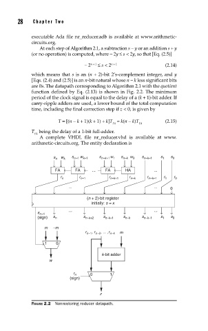
are 0s. The datapath corresponding to Algorithm 2.1 with the quotient
function defined by Eq. (2.13) is shown in Fig. 2.2. The minimum
period of the clock signal is equal to the delay of a (k + 1)-bit adder. If
carry-ripple adders are used, a lower bound of the total computation
time, including the final correction step if z < 0, is given by
T = [(n − k + 1)(k + 1) + k]T ≈ k(n − k)T (2.15)
FA FA
T being the delay of a 1-bit full-adder.
FA
A complete VHDL file nr_reducer.vhd is available at www.
arithmetic-circuits.org. The entity declaration is
s n w k s n–1 w k–1 s n–k+1 w 1 s n–k w 0 s n–k–1 s 1 s 0
FA FA ... FA HA ...
r n r n–1 r n–k+1 r n–k r n–k–1 r 1 r 0
... ...
0
(n + 2)-bit register
initially: s = x
... ...
s n+1
(sign) s n s n–k+2 s n–k+1 s n–k s n–k–1 s 1 s 0
m –m
, r , ... ,r
r n–1 n–2 n–k m
1 0
k-bit adder
w
r n 0 1
(sign)
z
FIGURE 2.2 Nonrestoring reducer datapath.