
Page 46 - Hardware Implementation of Finite-Field Arithmetic
P. 46
mod m Reduction 29
entity nr_reducer is
port (
x: in std_logic_vector (N downto 0);
m: in std_logic_vector(K-1 downto 0);
clk, reset, start: in std_logic;
z: out std_logic_vector (K-1 downto 0);
done: out std_logic
);
end nr_reducer;
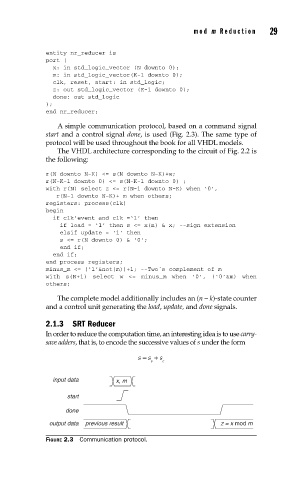
A simple communication protocol, based on a command signal
start and a control signal done, is used (Fig. 2.3). The same type of
protocol will be used throughout the book for all VHDL models.
The VHDL architecture corresponding to the circuit of Fig. 2.2 is
the following:
r(N downto N-K) <= s(N downto N-K)+w;
r(N-K-1 downto 0) <= s(N-K-1 downto 0) ;
with r(N) select z <= r(N-1 downto N-K) when ‘0’,
r(N-1 downto N-K)+ m when others;
registers: process(clk)
begin
if clk’event and clk =‘1’ then
if load = ‘1’ then s <= x(n) & x; --sign extension
elsif update = ‘1’ then
s <= r(N downto 0) & ‘0’;
end if;
end if;
end process registers;
minus_m <= (‘1’¬(m))+1; --Two´s complement of m
with s(N+1) select w <= minus_m when ‘0’, (‘0’&m) when
others;
The complete model additionally includes an (n − k)-state counter
and a control unit generating the load, update, and done signals.
2.1.3 SRT Reducer
In order to reduce the computation time, an interesting idea is to use carry-
save adders, that is, to encode the successive values of s under the form
s = s + s
s c
input data x, m
start
done
output data previous result z = x mod m
FIGURE 2.3 Communication protocol.