
Page 180 - High Power Laser Handbook
P. 180
148 Diode Lasers High-Power Diode Laser Arrays 149
emitter spacing to avoid thermal crosstalk, the step mirror is the best-
adapted solution to couple into a 100-mm-diameter fiber, even with an
NA of 0.12. The beam quality in the lateral direction is then given only
by the single emitter to 10 mm-mrad, and 8 to 10 emitters can be
stacked in the vertical direction. Demonstrations of 50 W from a single
bar and 100 W from two polarization-coupled bars have been done
from a 100-mm, 0.12-NA fiber for a single wavelength.
Beam Shaping with Refractive Optics
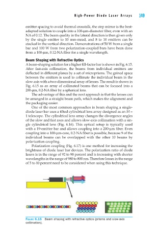
A beam-shaping solution for a higher fill-factor bar is shown in Fig. 6.15.
After fast-axis collimation, the beams from individual emitters are
deflected in different planes by a set of microprisms. The gained space
between the emitters is used to collimate the individual beam in the
slow axis with a two-dimensional array of lenses. The result is shown in
Fig. 6.15 as an array of collimated beams that can be focused into a
200-mm, 0.2-NA fiber by a spherical lens.
The advantage of this and the next approach is that the lenses can
be arranged in a straight beam path, which makes the alignment and
the packaging easier.
One of the most common approaches in beam shaping a single-
diode laser bar uses a tilted cylindrical lens array designed as an M =
1 telescope. The cylindrical lens array changes the divergence angles
of the slow and fast axes and allows slow-axis collimation with a sin-
gle cylindrical lens (Fig. 6.16). This optical setup is typically used
with a 19-emitter bar and allows coupling into a 200-mm fiber. Even
coupling into a 100-mm-core, 0.2-NA fiber is possible, because 9 of the
individual beams can be overlapped with the other 10 beams by
polarization coupling.
Polarization coupling (Fig. 6.17) is one method for increasing the
brightness of diode laser bar devices. The polarization ratio of diode
lasers is in the range of 92 to 98 percent and is increasing with shorter
wavelengths in the range of 980 to 800 nm. Therefore losses in the range
of 5 to 10 percent need to be considered when using this technique.
Figure 6.15 Beam shaping with refractive optics (prisms and slow-axis
collimation).