
Page 178 - High Power Laser Handbook
P. 178
146 Diode Lasers High-Power Diode Laser Arrays 147
Incident
Output beams
beams
High High
reflector reflector
A B
Incident Output
beams beams
High High
reflector reflector (1)
(1) B A (2)
(2) (3)
(3) (4)
(4) (5)
(5)
(a) (b)
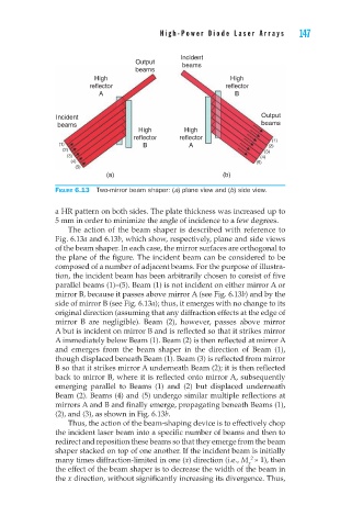
Figure 6.13 Two-mirror beam shaper: (a) plane view and (b) side view.
a HR pattern on both sides. The plate thickness was increased up to
5 mm in order to minimize the angle of incidence to a few degrees.
The action of the beam shaper is described with reference to
Fig. 6.13a and 6.13b, which show, respectively, plane and side views
of the beam shaper. In each case, the mirror surfaces are orthogonal to
the plane of the figure. The incident beam can be considered to be
composed of a number of adjacent beams. For the purpose of illustra-
tion, the incident beam has been arbitrarily chosen to consist of five
parallel beams (1)–(5). Beam (1) is not incident on either mirror A or
mirror B, because it passes above mirror A (see Fig. 6.13b) and by the
side of mirror B (see Fig. 6.13a); thus, it emerges with no change to its
original direction (assuming that any diffraction effects at the edge of
mirror B are negligible). Beam (2), however, passes above mirror
A but is incident on mirror B and is reflected so that it strikes mirror
A immediately below Beam (1). Beam (2) is then reflected at mirror A
and emerges from the beam shaper in the direction of Beam (1),
though displaced beneath Beam (1). Beam (3) is reflected from mirror
B so that it strikes mirror A underneath Beam (2); it is then reflected
back to mirror B, where it is reflected onto mirror A, subsequently
emerging parallel to Beams (1) and (2) but displaced underneath
Beam (2). Beams (4) and (5) undergo similar multiple reflections at
mirrors A and B and finally emerge, propagating beneath Beams (1),
(2), and (3), as shown in Fig. 6.13b.
Thus, the action of the beam-shaping device is to effectively chop
the incident laser beam into a specific number of beams and then to
redirect and reposition these beams so that they emerge from the beam
shaper stacked on top of one another. If the incident beam is initially
2
many times diffraction-limited in one (x) direction (i.e., M » 1), then
x
the effect of the beam shaper is to decrease the width of the beam in
the x direction, without significantly increasing its divergence. Thus,