
Page 177 - High Power Laser Handbook
P. 177
146 Diode Lasers High-Power Diode Laser Arrays 147
(b)
(c)
(a)
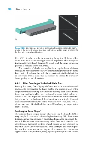
Figure 6.12 (a) Fast- and slow-axis collimation lens combination, (b) beam
profile in the far field without slow-axis collimation, and (c) beam profile in the
far field with slow-axis collimation.
(Fig. 6.12)—in other words, by increasing the optical fill factor of the
beam from 20 or 30 percent to greater than 90 percent. The divergence
is reduced to less than 3 degrees (50 mrad), and the beam parameter
product is reduced to 500 mm-mrad.
The majority of diode bar applications require beam delivery
through an optical fiber to conserve the initial brightness of the diode
laser device. To achieve this task, the beam of an individual diode bar
or the beams from a diode bar stack must be shaped to a uniform
beam quality in both directions.
6.6.1 Fiber Coupling of Individual Diode Bars
During the 1990s, four slightly different methods were developed
and used to homogenize the beam quality and preserve most of the
brightness before coupling into the beam delivery fiber. In addition to
these four methods which are explained in more detail below, an
alternate low-cost approach was also used that does not maintain the
brightness; this method coupled each emitter into a single fiber and
used the fiber bundle as part of the beam delivery. Thus, for a typical
diode laser bar, 19 individual fibers would be closely arranged in the
area of a circle.
6
Southampton Beam Shaper
The original beam shaper design (shown in Fig. 6.13a and 6.13b) is
very simple: It consists of only two high-reflectivity (HR) flat mirrors
that are aligned approximately parallel and separated by a small dis-
tance d. The mirrors are transversely offset from each other in both
directions, so that small sections of each mirror are not obscured by
the other. These unobscured sections form the input and output aper-
tures of the beam shaper. An improved version of the two-mirror
approach was designed later, using a plane parallel plate and adding