
Page 174 - High Power Laser Handbook
P. 174
142 Diode Lasers High-Power Diode Laser Arrays 143
Fast axis Slow axis
Cylindrical
lens
Diode bar
LuxxMaster TM
side view
Diode bar Cylindrical LuxxMaster TM
top view lens
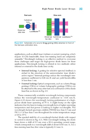
Figure 6.9 Schematic of a volume Bragg grating (VBG) attached in front of
the fast-axis collimation lens.
applications, such as alkali-laser (rubium or cesium) pumping, which
require 10 GHz bandwidth, these free-running lasers are completely
3
unusable. Wavelength locking is an effective method to overcome
these challenges and target the high-power diode lasers for these
applications. Wavelength locking is offered in two methods: either
internal or external to the diode laser cavity.
• Internal locking: A grating for selective spectral feedback is
etched in the structure of the semiconductor laser diode’s
4
active region. Internal gratings reduce the wavelength tem-
perature coefficient to 0.08 nm/K and can yield bandwidths
of less than 1 nm.
• External locking: Optical components, such as volume Bragg
gratings (VBGs) or volume holographic gratings (VHGs) can
be attached to the array after fast-axis collimation of the diode
laser bar, as shown in Fig. 6.9.
These commercially available wavelength locking components
reduce the wavelength–temperature coefficient to ~0.01 nm/K.
Figure 6.10 shows the wavelength locking performance of a high-
power diode laser operating at 75 A. A slight bump on the right
indicates that the laser is losing wavelength lock at higher operating
temperature and that power is leaking to higher wavelengths. The
wavelength-locked spectrum exhibits FWHM less than 0.5 nm and
FW 1/e of less than 1 nm throughout the entire temperature range
2
of 20 to 35°C.
The spectral stability of a wavelength-locked diode with respect
to current is shown in Fig. 6.11. With wavelength locking, the diode
laser shows a shift of 0.3 nm over a 20-A operating current range,
which corresponds to a wavelength shift of about 0.015 nm/A. For a
free-running laser bar, this value is typically 0.1 nm/A.