
Page 169 - High Power Laser Handbook
P. 169
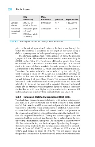
138    Diode Lasers                                                                                                    High-Power Diode Laser Arrays     139


                             Min.            Max.
                             Resistivity     Resistivity  pH Level  Expected Life
                  Vertical   200 kΩ-cm       500 kΩ-cm    6–7      > 10,000 hr
                  stacks     (pitch < 2 mm)
                  Horizontal   50 kΩ-cm (pitch   150 kΩ-cm   6–7   > 20,000 hr
                  or vertical   > 5 mm)
                  stacks     20 kΩ-cm (pitch
                             > 10 mm)

                 Table 6.1  Water Specifications for Actively Cooled Heat Sinks


                      pitch or the actual separation l  between the heat sinks through the
                                                s
                      water. The distance is described as the length of the water along a
                      dielectric passage (not including conducting spacers or manifolds).
                         In a standard vertical stack (with a pitch of 1.8 mm), the distance
                      l  equals 0.7 mm. The maximum recommended water resistivity is
                       s
                      500 kΩ-cm (see Table 6.1). The desired pH level of greater than 6 can
                      be  reached  with  a  mixed-bed  deionization  cartridge.  In  a  vertical
                      stack with spacers (plastic inserts in the water passage), the distance
                      l  is increased to the distance l , which includes the spacer thickness.
                       s
                                               sp
                      Therefore, the water resistivity can be reduced by the ratio of l /l sp
                                                                            s
                      until  reaching  a  value  of  100  kΩ-cm.  No  deionization  cartridge  is
                      needed in this case. The same holds for all horizontal stacks with a
                      typical distance l  of more than 10 mm. The increased distance for
                                     s
                      horizontal stacks enables reduced water specifications and increased
                      reliability  in  terms  of  the  heat  sink’s  expected  lifetime.  Horizontal
                      stacks can be arranged with integrated optics to achieve vertically
                      stacked beams with even higher brightness due to the increased fill
                      factor and greater reliability than vertical stacks (see Chap. 7).

                      6.3.2  Expansion-Matched Microchannel Heat Sinks
                      The diode laser bar can be mounted directly with indium to the copper
                      heat sink, or a CuW submount can be used to enable a hard solder
                      (AuSn). Both solutions will have an electrical potential in the water and
                      will need to follow the water specifications of Table 6.1. A new expan-
                      sion-matched mini-channel heat sink avoids the electrical potential in
                      the water and can therefore use any kind of coolant. The heat sink con-
                      sists of a copper-AlN sandwich. The top and bottom copper layers are
                      connected with an electrical feedthrough that is isolated from the cen-
                      ter cooling structure made of copper. The center part is isolated by two
                      AlN layers from the top and bottom layers. By adjusting the copper
                      thickness on top to about 80 mm, the expansion is matched to the coef-
                      ficient  of  GaAs  (6.5  10-6/°C),  as  the  coefficient  of AlN  is  about  4.5
                      10-6/°C  and  copper  is  about  16  10-6/°C.  The  top  copper  layer  is
                      designed to accommodate the anode as well as the cathode for the laser