
Page 167 - High Power Laser Handbook
P. 167
136 Diode Lasers High-Power Diode Laser Arrays 137
that reduce the stress on the bar and that can also carry other compo-
nents, such as the N contact and optical components. The reliable
AuSn solder joint approach offers an extended lifetime beyond 20,000
hours at higher operating currents, though with a slightly lower effi-
ciency due to the increased thermal impedance. Indium solder still
finds its application when highest efficiency and packaging density
are required by the application, such as in continuous operation (see
Sec. 6.4). Other submount materials, such as diamond and copper
diamond compounds, offer even higher thermal conductivity than
copper, but have poor electrical conductivity.
6.3 Heat Removal
The reliable output power of a high-power diode laser decreases with
increasing temperature of operation. Two basic approaches are used to
keep the temperature as low as possible. The first is to spread the heat
in a block of material with high thermal conductivity (e.g., Cu) before
removing the heat altogether (e.g., through transfer to air or water).
Typical dimensions of such heat sinks generally range from several
millimeters to a few centimeters; typical thermal impedance values are
2
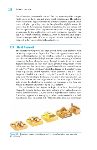
0.5 to 0.7°C/W for a 10 × 2 mm diode bar. Figure 6.3 illustrates various
types of passively cooled heat sink—most common is the 1 × 1 inch
footprint with different emission heights. The smaller footprint is typi-
cally used when multiple diodes are arranged in a horizontal array (see
Sec. 6.4). Because the heat is generated on the front edge of the heat
sink, where the diode bar is mounted, an extension to the front can
reduce the thermal impedance by up to 20 percent.
For applications that require multiple diode bars, the challenge
often is to arrange the bars in a small-volume array without compro-
mising the effectiveness (i.e., the thermal impedance) of the heat sink.
A standard approach is to employ modular, water-cooled (or active),
minichannel heat sinks (Fig. 6.4). This stackable, modular technology
Figure 6.3 Passively cooled heat sinks with 1 × 1 inch footprint, plus one with
10 × 25 mm .
2