Page 33 - High Power Laser Handbook
P. 33

6    G a s , C h e m i c a l , a n d F r e e - E l e c t r o n L a s e r s                                                   Carbon Dioxide Lasers      7


                      CO , can be explained by the larger difference in energy levels and
                         2
                      the  fact  that  CO  has  a  dipole  moment  and  thus  has  spontaneous
                      decay.
                         The energy transfer via N  and CO to CO  is much more efficient
                                                            2
                                               2
                      than the direct excitation of the CO  molecule; this is due to the much
                                                   2
                      larger cross sections for vibrational excitation of N  and CO by elec-
                                                                 2
                      tron impact. According to Hake and Phelps (1967), vibrational excita-
                      tion of CO  molecules by electron impact is only efficient for a narrow
                               2
                                            6
                      range of electron energies.  The vibrational excitation of CO and N
                                                                               2
                      by electron impact, however, is quite efficient for a wide range of elec-
                      tron  energies.  For  optimum  excitation  of  CO  and  N ,  the  electron
                                                                    2
                      energies should range from 1 to 3 electron volts (eV). The range of
                      electron energies can be adjusted by changing the pressure and com-
                                               2
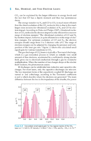
                      position of the laser gas mix.  Figure 1.3 shows the calculated small
                      signal gain for various transitions in CO .
                                                        2
                         The gas discharge of CO  lasers is typically a Townsend discharge,
                                             2
                      which  is  a  gas  ionization  process  in  which  an  initially  very  small
                      amount of free electrons, accelerated by a sufficiently strong electric
                      field, gives rise to electrical conduction through a gas by avalanche
                      multiplication. When the number of free charges drops or the electric
                      field weakens, the phenomenon ceases.
                         Rf discharges can be subdivided into inductive and capacitive dis-
                      charges. For most lasers, only the capacitive discharges are relevant.
                      The two important forms of the capacitively coupled RF discharge are
                      named  α-  and  γ-discharge,  according  to  the  Townsend  coefficients
                      α and γ, which describe where the electrons are generated.  The main
                                                                       4
                      difference between the two is the impedance of the sheaths, the power

                                                                   20
                         0.5
                                                    10R   20           10P
                               9R         9P
                                         20
                         0.4
                                 20
                                                            10   10
                        g 0  (m −1 )  0.3  10  10   J =   40            40

                         0.2   40            40
                                                                            50
                         0.1
                                                     60
                         0.0
                              9.2  9.4  9.6  9.8  10.0  10.2  10.4  10.6
                                                    λ (µm)
                      Figure 1.3  Calculated small-signal gain for the regular bands of the CO 2
                                                    –3
                      laser at T = 520 K; RF density = 5 Wcm ; He = 73%; and N 2  : CO 2  = 2.75. 19
   28   29   30   31   32   33   34   35   36   37   38