
Page 342 - High Power Laser Handbook
P. 342
310 So l i d - S t at e La s e r s Ultrafast Solid-State Lasers 311
8
6
Intensity (arb) 4
2
0
700 750 800 850 900
Wavelength (nm)
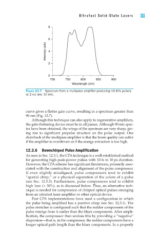
Figure 12.7 Spectrum from a multipass amplifier producing 16.8-fs pulses
at 2 mJ and 10 kHz.
curve gives a flatter gain curve, resulting in a spectrum greater than
90 nm (Fig. 12.7).
Although this technique can also apply to regenerative amplifiers,
the gain-flattening device must be in all passes. Although 90-nm spec-
tra have been obtained, the wings of the spectrum are very sharp, giv-
ing rise to significant prepulse structure on the pulse output. One
drawback of the multipass amplifier is that the beam quality can suffer
if the amplifier is overdriven or if the energy extraction is too high.
12.3.6 Downchirped Pulse Amplification
As seen in Sec. 12.3.1, the CPA technique is a well-established method
for generating high peak-power pulses with 10-fs to 10-ps duration.
However, the CPA scheme has significant limitations, primarily asso-
ciated with the construction and alignment of the pulse compressor.
If even slightly misaligned, pulse compressors tend to exhibit
“spatial chirp,” or a physical separation of the colors of a pulse
(see Sec. 12.3.3). Furthermore, pulse compressors tend to exhibit
high loss (> 30%), as is discussed below. Thus, an alternative tech-
nique is needed for compression of chirped optical pulses emerging
from an ultrafast laser amplifier or other optical device.
Past CPA implementations have used a configuration in which
the pulse being amplified has a positive chirp (see Sec. 12.3.1). The
pulse stretcher is configured such that the redder components of the
pulse emerge from it earlier than the bluer components. After ampli-
fication, the compressor then undoes this by providing a “negative”
dispersion—that is, in the compressor, the redder components have a
longer optical path length than the bluer components. In a properly