
Page 340 - High Power Laser Handbook
P. 340
308 So l i d - S t at e La s e r s Ultrafast Solid-State Lasers 309
where n(t, w) is the total amplification factor, and ∆N is the excited
state population. Because the small signal gain is exponential, the
17
frequencies at the edges of the gain bandwidth will see less gain than
will the center frequency. This effectively narrows the amplified spec-
trum, which, in turn, increases the compressed pulse duration. Other
factors, such as finite bandwidth mirror sets and other optical ele-
ments, can also reduce the overall bandwidth.
In high-intensity lasers, a nonlinear process that arises from the
amplified beam’s gaussian intensity distribution leads to a lensing
effect known as B integral. This effect is a nonlinear phase shift across
the beam profile:
w
ϕ() = 0 n ∫ I (, )dl (12.9)
t
tl
c 2
where n is the nonlinear index for a given material, and I(t, l) is the
2
beam intensity. B is the peak value of Eq. (12.9); in practice, B should
be kept to a minimum in the amplifier. Large amounts of B (much
greater than 1 rad) can lead to self-focusing and damage in the ampli-
fier or to filamentation outside the amplifier after compression.
Frequency pulling happens when the amplifier reaches satura-
tion. Because the red frequencies lead the blue in a positively chirped
pulse, it sees higher gain in saturation. This causes the peak of the
spectrum to red shift, which can be undesirable.
12.3.4 Regenerative Amplification
A regenerative amplifier (also known as a regen) is basically a stable
optical cavity with either an acousto-optic modulator (AOM) or an
electro-optic modulator (EOM) that switches pulses for a number of
gain passes and then extracts the amplified pulse out of the cavity.
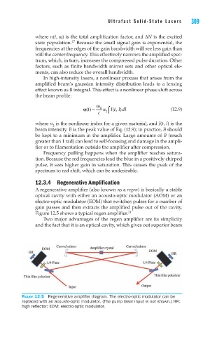
Figure 12.5 shows a typical regen amplifier. 21
Two major advantages of the regen amplifier are its simplicity
and the fact that it is an optical cavity, which gives out superior beam
Figure 12.5 Regenerative amplifier diagram. The electro-optic modulator can be
replaced with an acousto-optic modulator. (The pump laser input is not shown.) HR:
high reflector; EOM: electro-optic modulator.