
Page 336 - High Power Laser Handbook
P. 336
304 So l i d - S t at e La s e r s Ultrafast Solid-State Lasers 305
12.3.1 Chirped Pulse Amplification
CPA starts by “stretching” the low-energy pulse from an oscillator
by passing it through a 1:1 imaging system that contains a frequency-
separating element, such as a grating or prism. This imaging sys-
tem is then moved out of the imaging plane, leading to a different
path length for each frequency in the ultrafast pulse. This tech-
nique effectively “chirps” the pulse and can add 1 × 10 in stretch,
5
taking a 10-fs pulse to 100 to 1000 ps. After this stretching, ampli-
9
fication can be safely done to greater than 10 , or from 1 nJ to 1 J
(Fig. 12.2).
After amplification, recompression is done by a compressor,
which is typically a grating pair. The grating pair undoes the stretch
originally put on the pulses by the stretcher. In theory, the stretch put
on by a stretcher is given by 17,18
/
8 w 2 πL c 2 12
ϕw =− 1 − − sin g (12.3)
()
s
c wd
where ϕ (w) is the phase delay between the frequencies of light in
s
the pulse denoted by w, L is the length that the stretcher is detuned
from the focal plane, d is the grating groove spacing, and g is the
grating’s incident angle. Conversely, the grating pair compressor is
related simply by a change in sign and a factor of 2; for the stretcher
in Fig. 12.3, L is defined as deviation from the focal plane, whereas
in the compressor (Fig. 12.4), it is defined as the distance between
the gratings:
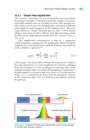
Figure 12.2 Diagram of chirped pulse amplification used to avoid damage
in ultrafast laser amplifier systems.