
Page 341 - High Power Laser Handbook
P. 341
310 So l i d - S t at e La s e r s Ultrafast Solid-State Lasers 311
quality. This can also be independent of the beam quality going into
the amplifier. Regen operation is quite simple: The stretched pulses
are injected through a thin film polarizer (TFP), where the EOM traps
the pulse in the cavity. The pulses amplify; when they reach their
peak, the other EOM switches the pulses out through a TFP. Typically
in a millijoule regen in Ti:sapphire, it takes about 20 to 40 passes to
amplify. Alternatively, a regen can be run with only one EOM and
one TFP, which then requires a Faraday isolator to prevent the output
from destroying back-stream optics.
Due to the large number of passes in the amplifier system and the
amount of refractive material, this scheme suffers from large phase
distortion. Therefore, it is difficult to recompress the pulses to less
than 50-fs durations without adverse effects. In addition, as the gain
changes (i.e., the pump laser power), the number of passes changes;
therefore, the compressor must adjust to compensate both angle and
separation. Although large bandwidths and short pulses have been
obtained by regen amplifiers, these pulses can “breathe,” due to small
environmental changes because the pulse spectrum is highly con-
fined by the phase distortion. 22,23
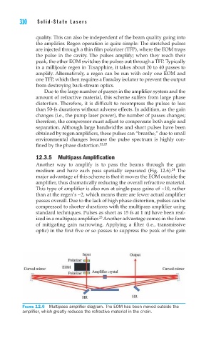
12.3.5 Multipass Amplification
Another way to amplify is to pass the beams through the gain
medium and have each pass spatially separated (Fig. 12.6). The
24
major advantage of this scheme is that it moves the EOM outside the
amplifier, thus dramatically reducing the overall refractive material.
This type of amplifier is also run at single-pass gains of ~10, rather
than at the regen’s ~2, which means there are fewer actual amplifier
passes overall. Due to the lack of high phase distortion, pulses can be
compressed to shorter durations with the multipass amplifier using
standard techniques. Pulses as short as 15 fs at 1 mJ have been real-
25
ized in a multipass amplifier. Another advantage comes in the form
of mitigating gain narrowing. Applying a filter (i.e., transmissive
optic) in the first five or so passes to suppress the peak of the gain
Figure 12.6 Multipass amplifier diagram. The EOM has been moved outside the
amplifier, which greatly reduces the refractive material in the chain.