
Page 456 - High Power Laser Handbook
P. 456
424 Fi b er L a s er s Intr oduction to Optical Fiber Lasers 425
0.50 0.6
0.45 Absorption 0.5 1.0
0.4
0.40
Cross section (pm 2 ) 0.30 Net cross section (pm 2 ) −0.1 0.6
0.8
Emission
0.3
0.35
0.2
0.4
0.1
0.2
0.25
0.0
0.20
0.05
0.15
0.10
−0.3
0.05 −0.2
−0.4
0.00 −0.5
1500 1700 1900 2100 1500 1700 1900 2100
Wavelength (nm) Wavelength (nm)
(a) (b)
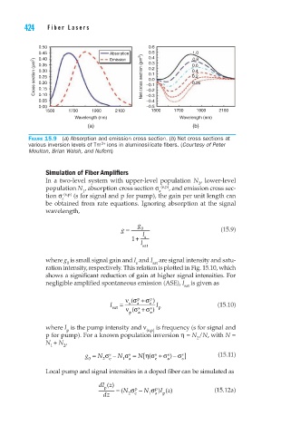
Figure 15.9 (a) Absorption and emission cross section. (b) Net cross sections at
3+
various inversion levels of Tm ions in aluminosilicate fibers. (Courtesy of Peter
Moulton, Brian Walsh, and Nufern)
Simulation of Fiber Amplifiers
In a two-level system with upper-level population N , lower-level
2
population N , absorption cross section σ a (s,p) , and emission cross sec-
1
tion σ e (s,p) (s for signal and p for pump), the gain per unit length can
be obtained from rate equations. Ignoring absorption at the signal
wavelength,
g
g = 0 (15.9)
1 + l s
l sat
where g is small signal gain and I and I are signal intensity and satu-
s
sat
0
ration intensity, respectively. This relation is plotted in Fig. 15.10, which
shows a significant reduction of gain at higher signal intensities. For
negligible amplified spontaneous emission (ASE), I is given as
sat
p
νσ p +σ )
(
I sat = s a s e s I (15.10)
p
(
p
e
νσ a +σ )
where I is the pump intensity and ν (s,p) is frequency (s for signal and
p
p for pump). For a known population inversion η = N /N, with N =
2
N + N ,
1 2
]
[(
g = N σ s − N σ s = N ησ s + σ s − σ ) s (15.11)
0 2 e 1 a e a a
Local pump and signal intensities in a doped fiber can be simulated as
dl z()
p = ( N σ p − N σ p ) Iz () (15.12a)
dz 2 e 1 a p