
Page 457 - High Power Laser Handbook
P. 457
424 Fi b er L a s er s Intr oduction to Optical Fiber Lasers 425
1.0
0.8
0.6
g/g 0
0.4
0.2
0.0
1.0E−03 1.0E−02 1.0E−01 1.0E+01 1.0E+02 1.0E+03
I/I sat
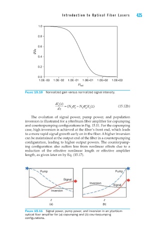
Figure 15.10 Normalized gain versus normalized signal intensity.
dl z()
s = ( N σ s − N σ s ) Iz () (15.12b)
dz 2 e 1 a s
The evolution of signal power, pump power, and population
inversion is illustrated for a ytterbium fiber amplifier for copumping
and counterpumping configurations in Fig. 15.11. For the copumping
case, high inversion is achieved at the fiber’s front end, which leads
to a more rapid signal growth early on in the fiber. A higher inversion
can be maintained at the output end of the fiber in a counterpumping
configuration, leading to higher output powers. The counterpump-
ing configuration also suffers less from nonlinear effects due to a
reduction of the effective nonlinear length or effective amplifier
length, as given later on by Eq. (15.17).
Pump Pump
Signal
Inversion
Signal
Inversion
z z
(a) (b)
Figure 15.11 Signal power, pump power, and inversion in an ytterbium
optical fiber amplifier for (a) copumping and (b) counterpumping
configurations.