
Page 50 - High Power Laser Handbook
P. 50
22 G a s , C h e m i c a l , a n d F r e e - E l e c t r o n L a s e r s Excimer Lasers 23
Reset
Power TR 1
supply L 1 L L C R
2 3 c c
C 0 C 1 C 2 C 3
C p D L 5
Trigger
IGBT
IGBT Solid state pulser Discharge
driver
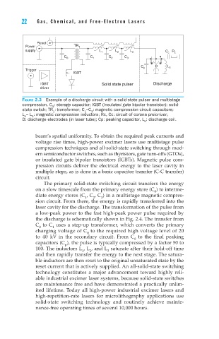
Figure 2.3 Example of a discharge circuit with a solid-state pulser and multistage
compression. C : storage capacitor; IGBT (insulated gate bipolar transistor): solid-
0
state switch; TR : transformer; C –C : magnetic compression circuit capacitors;
1
3
1
L – L : magnetic compression inductors; Rc, Cc: circuit of corona preionizer;
3
1
D: discharge electrodes (in laser tube); Cp: peaking capacitor, L : discharge coil.
5
beam’s spatial uniformity. To obtain the required peak currents and
voltage rise times, high-power excimer lasers use multistage pulse
compression techniques and all-solid-state switching through mod-
ern semiconductor switches, such as thyristors, gate turn-offs (GTOs),
or insulated gate bipolar transistors (IGBTs). Magnetic pulse com-
pression circuits deliver the electrical energy to the laser cavity in
multiple steps, as is done in a basic capacitor transfer (C-C transfer)
circuit.
The primary solid-state switching circuit transfers the energy
on a slow timescale from the primary energy store (C ) to interme-
0
diate energy stores (C , C , C ) in a multistage magnetic compres-
3
2
1
sion circuit. From there, the energy is rapidly transferred into the
laser cavity for the discharge. The transformation of the pulse from
a low-peak power to the fast high-peak power pulse required by
the discharge is schematically shown in Fig. 2.4. The transfer from
C to C uses a step-up transformer, which converts the primary
1
0
charging voltage of C to the required high voltage level of 20
0
to 40 kV in the secondary circuit. From C to the final peaking
0
capacitors (C ), the pulse is typically compressed by a factor 50 to
p
100. The inductors L , L , and L saturate after their hold-off time
2
1
3
and then rapidly transfer the energy to the next stage. The satura-
ble inductors are then reset to the original unsaturated state by the
reset current that is actively supplied. An all-solid-state switching
technology constitutes a major advancement toward highly reli-
able industrial excimer laser systems, because solid-state switches
are maintenance free and have demonstrated a practically unlim-
ited lifetime. Today all high-power industrial excimer lasers and
high-repetition-rate lasers for microlithography applications use
solid-state switching technology and routinely achieve mainte-
nance-free operating times of several 10,000 hours.