
Page 101 - High Temperature Solid Oxide Fuel Cells Fundamentals, Design and Applications
P. 101
78 High Temperature Solid Oxide Fuel Cells: Fundamentals, Design and Applications
h
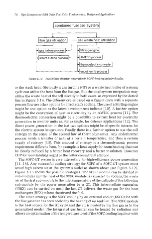
combined fuel cell system
.d cell waste heat utilisation I
thermoelectric converter
endothermic process
Figure 3.14 PossibiIities ofsystem integration in SOFGheat engine hybridcycles.
or the stack heat. Obviously a gas turbine (GT) or a waste heat boiler of a steam
cycle can utilise the heat from the flue gas. But the total system integration may
utilise the waste heat of the cell directly in both cases, as expressed by the dotted
line in Figure 3.14. The different cycles based on a Carnot cycle with a separate
process flow are other options for direct stack cooling. The use of a Stirling engine
might be one option as the latest developments indicate [lo]. A further option
might be the conversion of heat to electricity by an AMTEC process Ell]. The
thermoelectric conversion might be a possibility to extract heat for electricity
generation in smaller units as, for example, for defence applications [12]. The
direct power generation in the last two options might be of specific interest for
the electric system integration. Finally there is a further option to use the cell
entropy in the sense of the second law of thermodynamics. Any endothermic
process needs a transfer of heat at a certain temperature, and thus a certain
supply of entropy [13]. This amount of entropy is a thermodynamic process
requirement different from, for example, a heat supply for room heating that can
be clearly reduced by a better heat recovery and a better insulation. However
CHP for room heating might be the better commercial solution.
The SOFC-GT system is very interesting for high-efficiency power generation
[14-161. Any successful cooling strategy for SOFC of a SOFC-GT system must
avoid high excess air at the system's outlet as shown above (see Figure 3.12).
Figure 3.15 shows the possible strategies. The SOFC module can be divided in
sub-moduIes and the heat of the SOFC module is extracted by cooling the waste
air of the first sub-module to the inlet temperature of the cathode of the following
sub-module by the power generation by a GT. This intermediate expansion
(INEX) can be carried on until the last GT delivers the waste gas for the heat
exchangers (HEX) to heat the air and the fuel.
The other strategy is the SOFC cooling by an external cooler (EXCO) fed with
the flue gas that has been cooled by the heating of air and fuel. The SOFC module
is the heat source for the GT cycle and the air is heated by the flue gas as in the
generalised model. The integrated gas heater can be heated by radiation and
allows an optimisation of the temperature level of the SOFC cooling together with