
Page 97 - High Temperature Solid Oxide Fuel Cells Fundamentals, Design and Applications
P. 97
74 High Temperature Solid Oxide Fuel Cells: Fundamentals, Design and Appkations
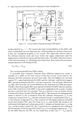
Figure 3.11 Process model for integrated reforming in SOFC systems.
be described by CFC < 1. The reasons for these irreversibilities of the SOFC and
other components are not important for understanding the system’s behaviour
if they are considered properly in the system. The important relation here is
the relation between work and heat within the single components and the
temperatures of the heat sources and the heat sinks. The SOFC is the heat source
of the fuel processing, i.e. reforming and evaporation. If we look at the necessary
temperature levels we find generally
This can be assumed for any SOFC system.
A reversible heat transport between these different temperature Ievels is
possible for a SOFC as the heat source of the two Carnot cycles and for the
reformer and the evaporator as their heat sinks. The real engines are: the heat
engine HE1, operating between the SOFC and the reformer, and the heat engine
HE2, operating between the SOFC and the evaporator. The exergetic efficiencies
I;HE (Eq. (SO)) describe the irreversibilities in the principal reversible processes.
Finally a third heat engine HE3 must operate between the SOFC and the ambient
state if the waste heat of the SOFC is not used completely in the system. The flue
gas flow is divided into two streams. The air is heated in the air heater AH by
cooling of the major stream of the flue gas (FGC). The reactant (of reforming) feed
water is heated in the economiser from the ambient temperature To to the
evaporator temperature Tevap and the saturated steam is superheated from Tevap
to the reformer temperature T,,p The reactant (of reforming) methane is heated
in the fuel heaters FH1 and FH2 from TO to Tref and finally the products (of
reforming) hydrogen and carbon monoxide (+ steam) are heated from T,,f to the
Tsopc in the product heater PH. The required heat is supplied by the cooling of
the second pass of the flue gas (FGC) from Tsopc to a waste gas temperature > To,
by the SOFC directly (for PH), by the waste heat of HE1 (for T < T,,f) and by