
Page 102 - High Temperature Solid Oxide Fuel Cells Fundamentals, Design and Applications
P. 102
Thermodynamics 79
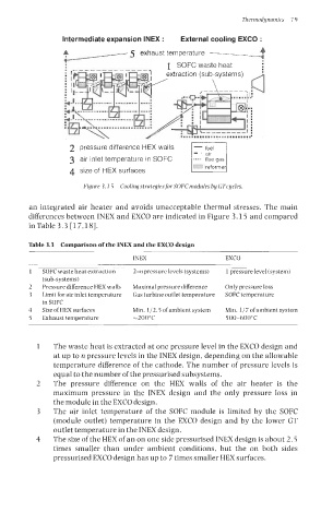
Intermediate expansion INEX : External cooling EXCO :
A 5 exhaust temperature -?
*
1 SOFC waste heat
2 pressure difference HEX walls - fuel
3 air inlet temperature in SOFC
reforme
4 size of HEX surfaces
Figure 3. I 5 Coolingstrategiesfor SOFC modules by GTcycles.
an integrated air heater and avoids unacceptable thermal stresses. The main
differences between INEX and EXCO are indicated in Figure 3.15 and compared
in Table 3.3 [ 17,181.
Table 3.3 Comparison of the INEX and the EXCO design
INEX EXCO
1 SOFC waste heat extraction 2-n pressure levels (systems) 1 pressure level (system)
(sub-systems)
2 Pressure difference HEX walls Maximal pressure difference Only pressure loss
3 Limit for air inlet temperature Gas turbine outlet temperature SOFC temperature
in SOFC
4 Size of HEX surfaces Min. 1j2.5 ofambient system Min. 1/7 ofambientsystem
5 Exhaust temperature -200°C 500-600°C
1 The waste heat is extracted at one pressure level in the EXCO design and
at up to n pressure levels in the INEX design, depending on the allowable
temperature difference of the cathode. The number of pressure levels is
equal to the number of the pressurised subsystems.
2 The pressure difference on the HEX walls of the air heater is the
maximum pressure in the INEX design and the only pressure loss in
the module in the EXCO design.
3 The air inlet temperature of the SOFC module is limited by the SOFC
(module outlet) temperature in the EXCO design and by the lower GT
outlet temperature in the INEX design.
4 The size of the HEX of an on one side pressurised INEX design is about 2.5
times smaller than under ambient conditions, but the on both sides
pressurised EXCO design has up to 7 times smaller HEX surfaces.