
Page 286 - High Temperature Solid Oxide Fuel Cells Fundamentals, Design and Applications
P. 286
Testing of Electrodes, Cells and Short Stacks 263
a 1OOOpm
I
T Ennllm
50pm I
4-
1Opm *
500pm
i
I
b
1
A true reference
electrode should
placed
here
be
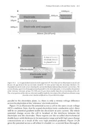
Figure 10.1 (a) A typical sketch of an electrode-supported cell. Note that such an illustration is out of scale
because the gap between the top electrodes should be 50 times greater than the electrolyte thickness. (b)
Expanded view ofelectrode corners showing the current distribution indicated by schematic current lines. The
current density, apart from being approximately parallel to the electrolyte plane, is very small at the position
of the ‘reference’ electrode, at least 50 (500 WmllO Wm) times smaller than the current density of the cell.
Thecorrectpositionofthe referenceelectrode wouldbeinside theelectrolyteofthecell andsomedistanceaway
from thecorner, but thisisdificult ina 10~m thickelectrolyte.
parallel to the electrolyte plane, i.e. there is only a minute voltage difference
across the electrolyte at the ‘reference’ electrode position.
Figure 10.2a illustrates the potential across a cell in the open circuit voltage
(OCV) condition. Note, that for a good electrolyte (ionic conduction only), there
will be no potential gradient inside the electrolyte at zero current. The whole
potential change across the cell is localised at the interfaces between the
electrolyte and the electrodes. These regions are the so-called electrochemical
double layers with thickness in the nanometre range and with high space charge
concentrations as a result of the very high potential gradients. Figure 10.2b
gives the potential across a cell when it is loaded, i.e. a current flows through it.