
Page 290 - High Temperature Solid Oxide Fuel Cells Fundamentals, Design and Applications
P. 290
Testing ofElectrodes, Cells and Short Stacks 267
Pt paste
Composite electrode
Electrolyte
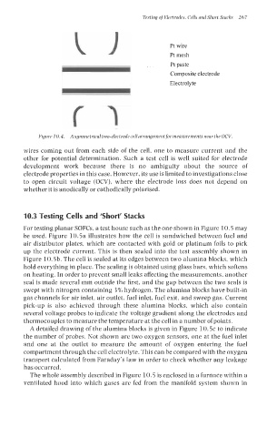
Figure 10.4. A symmetrical two-electrode cell arrangementfor measurements near the OCV.
wires coming out from each side of the cell, one to measure current and the
other for potential determination. Such a test cell is well suited for electrode
development work because there is no ambiguity about the source of
electrode properties in this case. However, its use is limited to investigations close
to open circuit voltage (OCV), where the electrode loss does not depend on
whether it is anodically or cathodically polarised.
10.3 Testing Cells and ‘Short’ Stacks
For testing planar SOFCs, a test house such as the one shown in Figure 10.5 may
be used. Figure 10.5a illustrates how the cell is sandwiched between fuel and
air distributor plates, which are contacted with gold or platinum foils to pick
up the electrode current. This is then sealed into the test assembly shown in
Figure 10.5b. The cell is sealed at its edges between two alumina blocks, which
hold everything in place. The sealing is obtained using glass bars, which softens
on heating. In order to prevent small leaks affecting the measurements, another
seal is made several mm outside the first, and the gap between the two seals is
swept with nitrogen containing 3% hydrogen. The alumina blocks have built-in
gas channels for air inlet, air outlet, fuel inlet, fuel exit, and sweep gas. Current
pick-up is also achieved through these alumina blocks, which also contain
several voltage probes to indicate the voltage gradient along the electrodes and
thermocouples to measure the temperature at the cell in a number of points.
A detailed drawing of the alumina blocks is given in Figure 10.5~ indicate
to
the number of probes. Not shown are two oxygen sensors, one at the fuel inlet
and one at the outlet to measure the amount of oxygen entering the fuel
compartment through the cell electrolyte. This can be compared with the oxygen
transport calculated from Faraday’s law in order to check whether any leakage
has occurred.
The whole assembly described in Figure 10.5 is enclosed in a furnace within a
ventilated hood into which gases are fed from the manifold system shown in