
Page 292 - High Temperature Solid Oxide Fuel Cells Fundamentals, Design and Applications
P. 292
Testing oJElectrodes, Cells and Short Stacks 269
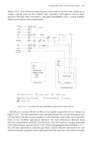
Figure 10.6. This allows a range of gases to be used on the fuel side, while air or
oxygen can be used on the oxidant side. Typically, hydrogen is used as fuel,
metered through flow controllers, and then humidified with a water bubbler
before entering the cell compartment.
I
Ventilation
Sample Temp
Cell house
Safety box DT Furnace
Ventilated hood
.........................~~.....
@ Reduction valve Contra valve 0 Safety valve
MFC: Mass Flow Controller M: Bore Flow Rator D: Detector
2-way valve
Figure 10.6 Schematic ofthe gas manijolding arrangement for single-cell tests,
Results of a recent cell test at Ris0 of an anode-supported cell are shown in
Figure 10.7. The fuel utilisation was calculated from the current flowing in the
cell and also from the oxygen analysis at the fuel inlet and outlet. It is seen that
there is an excellent agreement between the fuel utilisations derived from
the two independent methods. Furthermore, the OCV and the oxygen potential
ofthe inlet fuel gas agreed within 1 mV. When obtaining the data in Figure 10.7,
the cell was operated at constant gas flows, which may be convenient for cell
characterisation purposes, but is obviously not the way the cells will eventually