
Page 111 - Human Inspired Dexterity in Robotic Manipulation
P. 111
Approaching Human Hand Dexterity Through Highly Biomimetic Design 109
the two servos to bend and straighten the coupled fingers approximately
once every 2 s. The coordinates of the reflective markers attached to the fin-
gertip are recorded by a motion capture system (Vicon Bonita) composed of
seven infrared cameras at 240 Hz VGA resolution. The Vicon system was
calibrated, and is able to detect 0.5 mm displacement in all directions.
To avoid the marker occlusion and confusion issues, we attached a fore-
arm frame (see Fig. 6.17) near the wrist of our robotic hand, so that we could
record the marker trajectories for one fingertip at a time, and then transform
their coordinates from the default world frame to this forearm frame when
processing the data. The use of this forearm frame also allows us to constantly
change the orientation of our robotic hand during hand motions to achieve
good visibility for the reflective markers.
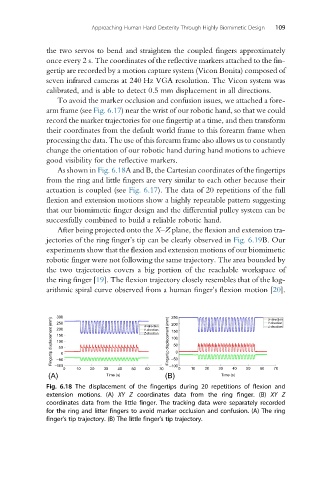
As shown in Fig. 6.18A and B, the Cartesian coordinates of the fingertips
from the ring and little fingers are very similar to each other because their
actuation is coupled (see Fig. 6.17). The data of 20 repetitions of the full
flexion and extension motions show a highly repeatable pattern suggesting
that our biomimetic finger design and the differential pulley system can be
successfully combined to build a reliable robotic hand.
After being projected onto the X–Z plane, the flexion and extension tra-
jectories of the ring finger’s tip can be clearly observed in Fig. 6.19B. Our
experiments show that the flexion and extension motions of our biomimetic
robotic finger were not following the same trajectory. The area bounded by
the two trajectories covers a big portion of the reachable workspace of
the ring finger [19]. The flexion trajectory closely resembles that of the log-
arithmic spiral curve observed from a human finger’s flexion motion [20].
300 250
Fingertip displacement (mm) 150 0 Fingertip displacement (mm) 150 0
250
200
200
100
100
50
50
–50
–50
–100
0 10 20 30 40 50 60 70 –100 0 10 20 30 40 50 60 70
(A) Time (s) (B) Time (s)
Fig. 6.18 The displacement of the fingertips during 20 repetitions of flexion and
extension motions. (A) XY Z coordinates data from the ring finger. (B) XY Z
coordinates data from the little finger. The tracking data were separately recorded
for the ring and litter fingers to avoid marker occlusion and confusion. (A) The ring
finger’s tip trajectory. (B) The little finger’s tip trajectory.