
Page 132 - Hybrid Enhanced Oil Recovery Using Smart Waterflooding
P. 132
124 Hybrid Enhanced Oil Recovery using Smart Waterflooding
modeling changes the two-phase relative permeability depletion and CO 2 injection is investigated. The
as a function of salinity-dependent contact angle. pressure-temperature diagram of phase behavior of
Because the CO 2 WAG process incorporates the asphaltene indicates no possibility of asphaltene
three-phase flow of oil, water, and gas, the Baker’s precipitation even with CO 2 injection at reservoir
model (Baker, 1988) is used for the three-phase relative temperature.
permeability of mixed-wet formation. In the Baker’s Before the simulation of LS-CO 2 EOR, the secondary
model, the three-phase oil relative permeability is seawater injection and tertiary CO 2 injection or
obtained by the saturation-weighted interpolation conventional CO 2 WAG process using seawater are
between two-phase relative permeabilities of oil/water simulated. The seawater has the salinity of
and oil/gas. The empirical approach of LSWF 43,610 ppm TDS. It has viscosity of 0.26 cp at reservoir
mechanism modifies the endpoint and Corey’s temperature of 248 F. The oil and CO 2 gas have
exponent of oil corresponding only two-phase relative viscosities of 1.05 cp and 0.043688 cp at reservoir
permeability of oil/water as well as residual oil satura- temperature. After the seawater injection, the equal
tion, then three-phase oil relative permeability amount of CO 2 is injected for tertiary CO 2 injection
of Baker’s model is determined by incorporating the and conventional CO 2 WAG process. It is observed
LSWF mechanism. In terms of modeling of CO 2 WAG that either CO 2 injection or conventional CO 2 WAG
process, the MMP of oil is calculated to determine recovers the additional oil over secondary injection. A
whether the CO 2 WAG process is miscible or number of designs of low salinityeaugmented CO 2
immiscible condition. The software of PVTsim, PVT injection are simulated with varying injection scheme
simulator developed by Calsep Inc., and UTCOMP and salinity. The low-salinity water is prepared by
simulate the slim tube test to determine the MMP of diluting the seawater. The injection schemes of
oil at reservoir temperature of 248 F. The MMP is CO 2 include the CGI, simultaneous water and CO 2
estimated as 3400 psi. The bubble point pressure gas injection (SWAG), constant WAG, and tapered
is also calculated and determined as 3700 psi. It is WAG. The SWAG, constant WAG, and tapered WAG
unusual to have higher bubble point pressure use the low-salinity water for the water injection.
than MMP of oil. Considering the uncertainty in the Regardless of injection schemes of CO 2 , additional oil
calculation of bubble point pressure and MMP, the recovery is obtained over the secondary oil recovery.
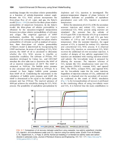
MMP is determined to be equal to the bubble point As confirmed in the result of SWAG simulation
pressure and has 3700 psi. The reservoir pressure of (Fig. 5.7), the increased tertiary oil recovery is attributed
4000 psi achieves the miscibility during the CO 2 WAG to the combining effects of using low-salinity water
process. The possibility of asphaltene precipitation by and CO 2 . It is believed that the main contribution to
FIG. 5.7 Comparison of oil recovery between waterflood using seawater, low-salinity waterflood, miscible
CO 2 injection, and simultaneous water and CO 2 injection using low-salinity water. (Credit: From Al-Shalabi,
E. W., Sepehrnoori, K., & Pope, G. (2016). Numerical modeling of combined low salinity water and carbon
dioxide in carbonate cores. Journal of Petroleum Science and Engineering, 137, 157e171. https://doi.org/10.
1016/j.petrol.2015.11.021.)