
Page 208 - Hybrid-Renewable Energy Systems in Microgrids
P. 208
188 Hybrid-Renewable Energy Systems in Microgrids
2.5.3 Effect of rotor resistance
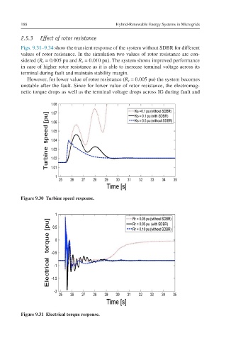
Figs. 9.31–9.34 show the transient response of the system without SDBR for different
values of rotor resistance. In the simulation two values of rotor resistance are con-
sidered (R = 0.005 pu and R = 0.010 pu). The system shows improved performance
r
r
in case of higher rotor resistance as it is able to increase terminal voltage across its
terminal during fault and maintain stability margin.
However, for lower value of rotor resistance (R = 0.005 pu) the system becomes
r
unstable after the fault. Since for lower value of rotor resistance, the electromag-
netic torque drops as well as the terminal voltage drops across IG during fault and
Figure 9.30 Turbine speed response.
Figure 9.31 Electrical torque response.