
Page 230 - Hydrocarbon
P. 230
Reservoir Dynamic Behaviour 217
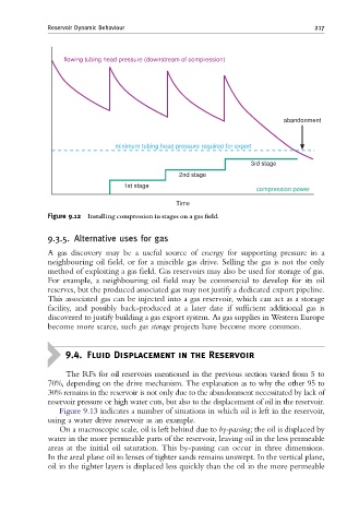
flowing tubing head pressure (downstream of compression)
abandonment
minimum tubing head pressure required for export
3rd stage
2nd stage
1st stage
compression power
Time
Figure 9.12 Installing compression in stages on a gas ¢eld.
9.3.5. Alternative uses for gas
A gas discovery may be a useful source of energy for supporting pressure in a
neighbouring oil field, or for a miscible gas drive. Selling the gas is not the only
method of exploiting a gas field. Gas reservoirs may also be used for storage of gas.
For example, a neighbouring oil field may be commercial to develop for its oil
reserves, but the produced associated gas may not justify a dedicated export pipeline.
This associated gas can be injected into a gas reservoir, which can act as a storage
facility, and possibly back-produced at a later date if sufficient additional gas is
discovered to justify building a gas export system. As gas supplies in Western Europe
become more scarce, such gas storage projects have become more common.
9.4. Fluid Displacement in the Reservoir
The RFs for oil reservoirs mentioned in the previous section varied from 5 to
70%, depending on the drive mechanism. The explanation as to why the other 95 to
30% remains in the reservoir is not only due to the abandonment necessitated by lack of
reservoir pressure or high water cuts, but also to the displacement of oil in the reservoir.
Figure 9.13 indicates a number of situations in which oil is left in the reservoir,
using a water drive reservoir as an example.
On a macroscopic scale, oil is left behind due to by-passing; the oil is displaced by
water in the more permeable parts of the reservoir, leaving oil in the less permeable
areas at the initial oil saturation. This by-passing can occur in three dimensions.
In the areal plane oil in lenses of tighter sands remains unswept. In the vertical plane,
oil in the tighter layers is displaced less quickly than the oil in the more permeable