
Page 232 - Hydrocarbon
P. 232
Reservoir Dynamic Behaviour 219
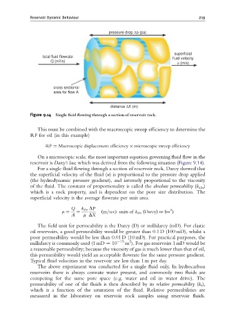
pressure drop Δp (pa)
superficial
total fluid flowrate fluid velocity
Q (m 3 /s)
u (m/s)
cross sectional
area for flow A
distance ΔX (m)
Figure 9.14 Single £uid £owing through a section of reservoir rock.
This must be combined with the macroscopic sweep efficiency to determine the
RF for oil (in this example)
RF ¼ Macroscopic displacement efficiency microscopic sweep efficiency
On a microscopic scale, the most important equation governing fluid flow in the
reservoir is Darcy’s law, which was derived from the following situation (Figure 9.14).
For a single fluid flowing through a section of reservoir rock, Darcy showed that
the superficial velocity of the fluid (u) is proportional to the pressure drop applied
(the hydrodynamic pressure gradient), and inversely proportional to the viscosity
of the fluid. The constant of proportionality is called the absolute permeability (k abs )
which is a rock property, and is dependent on the pore size distribution. The
superficial velocity is the average flowrate per unit area.
Q k abs DP 2
m ¼ ¼ ðm=secÞ units of k abs ðDarcyÞ or ðm Þ
A m DX
The field unit for permeability is the Darcy (D) or millidarcy (mD). For clastic
oil reservoirs, a good permeability would be greater than 0.1 D (100 mD), whilst a
poor permeability would be less than 0.01 D (10 mD). For practical purposes, the
15 2
millidarcy is commonly used (1 mD ¼ 10 m ). For gas reservoirs 1 mD would be
a reasonable permeability; because the viscosity of gas is much lower than that of oil,
this permeability would yield an acceptable flowrate for the same pressure gradient.
Typical fluid velocities in the reservoir are less than 1 m per day.
The above experiment was conducted for a single fluid only. In hydrocarbon
reservoirs there is always connate water present, and commonly two fluids are
competing for the same pore space (e.g. water and oil in water drive). The
permeability of one of the fluids is then described by its relative permeability (k r ),
which is a function of the saturation of the fluid. Relative permeabilities are
measured in the laboratory on reservoir rock samples using reservoir fluids.